Gigabyte 7014 user manual Din Rail Mounting, page 11 of

Models: 7014

1 152
Download 152 pages 9 Kb
Page 11
Image 11
DIN RAIL MOUNTING

DIN RAIL MOUNTING

Install the unit on a standard 35mm Din-Rail. Recess the 7014TX unit to allow at least 3” of horizont al clearance for fiber cable bend radius. Recess the 7014FX2 unit to allow at least 5” of horizontal clearance for fiber cable ben d radius.

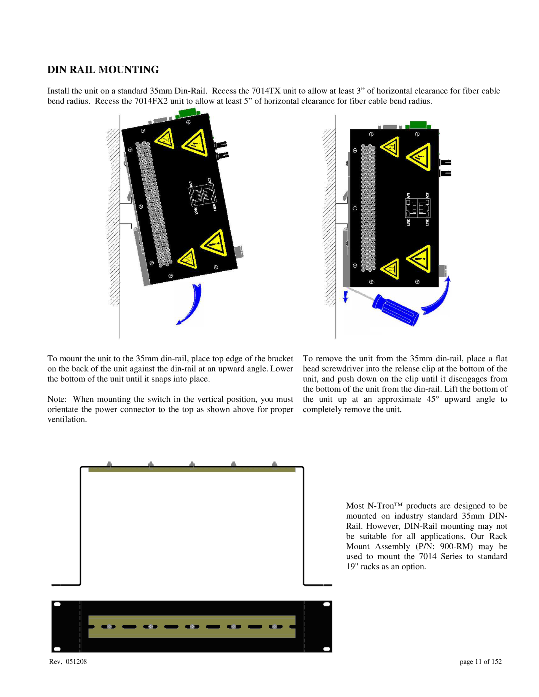
To mount the unit to the 35mm din-rail, place top edge of the bracket on the back of the unit against the din-rail at an upward angle. Lower the bottom of the unit until it snaps into place.

Note: When mounting the switch in the vertical position, you must orientate the power connector to the top as shown above for proper ventilation.

To remove the unit from the 35mm din-rail, place a flat head screwdriver into the release clip at the bottom of the unit, and push down on the clip until it disengages from the bottom of the unit from the din-rail. Lift the bottom of the unit up at an approximate 45° upward angle to completely remove the unit.

Most N-Tron™ products are designed to be mounted on industry standard 35mm DIN- Rail. However, DIN-Rail mounting may not be suitable for all applications. Our Rack Mount Assembly (P/N: 900-RM) may be used to mount the 7014 Series to standard 19" racks as an option.

Rev. 051208

page 11 of 152

Page 11
Image 11
Gigabyte 7014 user manual Din Rail Mounting, page 11 of