SERIAL INTERFACE
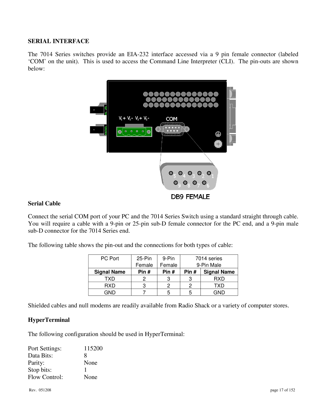
The 7014 Series switches provide an
Serial Cable
Connect the serial COM port of your PC and the 7014 Series Switch using a standard straight through cable. You will require a cable with a
The following table shows the
PC Port | 7014 series | ||||
| Female | Female |
| ||
Signal Name | Pin # | Pin # | Pin # |
| Signal Name |
TXD | 2 | 3 | 3 |
| RXD |
RXD | 3 | 2 | 2 |
| TXD |
GND | 7 | 5 | 5 |
| GND |
Shielded cables and null modems are readily available from Radio Shack or a variety of computer stores.
HyperTerminal
The following configuration should be used in HyperTerminal:
Port Settings: | 115200 |
Data Bits: | 8 |
Parity: | None |
Stop bits: | 1 |
Flow Control: | None |
Rev. 051208 | page 17 of 152 |