HP Part No. A4200-90014 Edition E0995
Model C100/110 Owner’s Guide
Page
Contents
Monitors Keyboards
Operating the CD-ROM Drive
Using Your CD-ROM Drive
Operating the DDS Tape Drive
Using Your Digital Data Storage DDS Tape Drive
Operating the Floppy Drive
Using Your 3.5-Inch Floppy Disk Drive
Safety and Regulatory Statements
Solving Problems
Changing Your Workstation’s Hardware Configuration
Replacing the Battery Changing Your Monitor Type
Scsi Connections
Boot Console Interface
Displaying the Current Memory Configuration
Figures
Xiii
Xiv
Tables
Xvi
System Overview
System Overview
Product Description
This workstation has the following key features
EISA/GSC
System Unit Front Panel Controls
System Unit Front Panel Controls and LEDs
Power LED
System Power Switch
Use the Power switch to power the system unit on and off
Power LED lights when the system unit power is on
Next to the system LEDs are the following audio controls
Removable Storage Devices
Audio Controls
System Unit Rear Panel Connectors
Security Loop
System Unit Rear Panel Connectors
Audio Connectors
Audio Electrical Specifications
Signal to Noise
Frequency Response 25-20,000 Hz Input Sensitivity/Impedance
Max Output Level/Impedance
HP Parallel I/O Connector
Keyboard Connectors
Network Connectors
Serial I/O Connectors
Serial I/O Pins Pin No Signal Description
Scsi Connectors
TOC Button
Power Cord Connector
You can use one of two HP monitors with your workstation
Monitors
Keyboard Differences
Keyboards
PS2 Keyboard and ITF Keyboard Equivalent Keys
PS/2 Keycap Symbol ITF Keycap Symbol
Keyboards
Pointing Devices
Operating System Overview
Lanic ID
Important Information You Need to Note
Lanic ID in this example is 0800091595EE
Terminal Control
You will see a table similar to Table
Scsi ID and Device File Information for HP-UX
Default device file names for your drives are listed below
Device
CD-ROM drive
IP Address and Subnetwork Mask Information
For installation on a system permitting long file names
For installation on a system requiring short file names
Mail
Networking Overview
Telnet
Man telnet
Rcp
Rlogin
Ftp
Setting Up Your Printer
Setting Up Your Printer
Gathering Printer Information
Opening the General Toolbox
Setting Up a Local Printer Using SAM
Opening the Toolbox Subpanel
Executing the SAM Icon
Opening the SystemAdmin Toolbox
Click on Printer/Model Interface
Setting Up a Local Printer Using SAM
Lp -dprintername .vueprofile
Lp .vueprofile
Usr/sbin/inetd.conf
Setting Up Your Printer for Network Printing
Etc/inetd.conf
Usr/sbin/reboot
Etc/reboot
Man lp
Printing a File
If you have problems printing, check the following
Solving Printer Problems
Using Your CD-ROM Drive
Using Your CD-ROM Drive
CD-ROM Drive
CD-ROM Drive and CD-ROM Media Descriptions
CD-ROM Drive Controls and Features
Controls and Features
Control/Feature Purpose
CD-ROM Drive Operating Controls and Features
Caring for CD-ROM Discs
CD-ROM Media
Loading and Unloading a CD-ROM in the Disc Tray
Operating the CD-ROM Drive
Disc Tray Description
CD-ROM Disc Tray
Placing a CD-ROM Disc in a Horizontally Mounted Drive
Loading a CD-ROM Disc in a Horizontally Mounted Drive
Removing a CD-ROM Disc From a Horizontally Mounted Drive
Unloading a CD-ROM Disc in a Horizontally Mounted Drive
Releasing the Disc Holder Retainers
To load a disc in the CD-ROM drive, follow these steps
Loading a CD-ROM Disc in a Vertically Mounted Drive
Placing a CD-ROM Disc in a Vertically Mounted Drive
Removing a CD-ROM Disc From a Vertically Mounted Drive
Unloading a CD-ROM Disc in a Vertically Mounted Drive
Etc/ioscan -d scsi
Verifying the CD-ROM Drive Operation
Usr/sbin/ioscan -d sdisk
If you receive this message, go to , Solving Problems
Using Device Files
Mounting and Unmounting a CD-ROM Disc
Mounting a CD-ROM Disc Using SAM
Toolbox Arrow
From the Actions menu, click on Add a Hard Disk Drive
Peripheral Devices
Systems
Unmounting a CD-ROM Disc Using SAM
Following screen message appears
Disks and File Systems window opens. Double-click on CD-ROM
Floppy, and Hard Disks
Reading the Busy Light
Defective disc
Troubleshooting
Troubleshooting
Using Your Digital Data Storage DDS Tape Drive
Using Your Digital Data Storage DDS Tape Drive
DDS Drive Controls and Indicators
Controls and Indicators
DDS Tape Drive and Data Cassette Descriptions
DDS Drive
LEDs
LED Warning Conditions
DDS Tape Drive LED Display Codes
Media Life
Data Cassettes
Media Restrictions
Setting the Write-Protect Tab on a Data Cassette
Cleaning the Tape Heads
Push tab right for write Push tab left for write-protect
Setting the Write-Protect Tab on a DDS Tape
Loading and Unloading a Data Cassette
Operating the DDS Tape Drive
Loading and Unloading a Data Cassette
Verifying the DDS Tape Drive Operation
If you are using HP-UX 10.0, enter the following
Etc/ioscan -d scsi
Usr/sbin/ioscan -d stape
Device Files Data Compression
Device Files No Data Compression
Writing to a Data Cassette
Archiving Data in Compressed and Noncompressed Mode
Listing the Files on a Data Cassette
Restoring Files from a Data Cassette to Your System
Terminal window opens
Tar -cvf /dev/rmt/3m pathname
Media Interchangeability Restrictions
Further Command Information
Tar -tvf /dev/rmt/3m
Man tar
Troubleshooting
Ordering Information
Using Your 3.5-Inch Floppy Disk Drive
Using Your 3.5-Inch Floppy Disk Drive
Setting the Write-Protect Tab on a Floppy Diskette
Using the Floppy Diskette
Setting the Write-Protect Tab on a Diskette
Inserting and Removing a Floppy Diskette
Inserting and Removing a Diskette
Etc/ioscan for
Verifying the Floppy Drive Configuration
Operating the Floppy Drive
Dev/rfloppy/c20Ad1s0
Mediainit -i 2 /dev/rfloppy/c20Ad1s0
Formatting a New Diskette
Saving Files to a Floppy Diskette
Transferring Data To and From a Floppy Diskette
Tar -cvf /dev/rfloppy/c20Ad1s0 pathname
Restoring Files from a Floppy Diskette to Your System
Tar -tvf /dev/rfloppy/c20Ad1s0
Listing the Files on a Floppy Diskette
Tar -xvf /dev/rfloppy/c20Ad1s0 pathname
For More Information
Configuring the Floppy Driver
Troubleshooting
Ordering Information
Solving Problems
Solving Problems
Problems with Powering Up the System
Common Problems and Solutions
Power Up Problems
Problem Solution
Problems with the 802.3 Network
Problems Loading and Booting the Operating System
Work and offers solutions
Problems Loading and Booting the Operating System
Problems Using a Hard Disk Drive
Problems Using a Hard Disk Drive
Drive and offers solutions
Problems Using the CD-ROM Drive
Problems Using the CD-ROM Drive
Problems Using the DDS Tape Drive
Problems Using the DDS Tape Drive
Tape drive and offers solutions
Problems Using the Floppy Disk Drive
Problems Using the Floppy Disk Drive
Dealing with a Boot Failure
Man cstm Man mstm Man xstm
Running System Verification Tests
Following screen appears
Cstm
Following messages appear
Cstm verify all
Safety and Regulatory Statements
106
Federal Communications Commission FCC
Emissions Regulations
Acoustics
Emissions Regulations Compliance
Vcci Class 2 ITE
Regulation On Noise Declaration For Machines -3. Gsgv
Electrostatic Discharge ESD Precautions
This equipment conforms to the following safety standards
Safety Statement
Laser Safety Statement U.S.A. Only
112
Changing Your Workstation’s Hardware Configuration
Also, read the ESD Precautions in Appendix a of this guide
Usr/sbin/ioscan -f
Checking the Scsi IDs
116
Preparing Your Workstation
Removing the Floor Stand
Installing Storage Devices
Came with your device
Preparing to Install Your Storage Device
Tray Supported Devices Conditions Position
Disk Tray Positions Storage Configurations
Mounting the Storage Device Slides
Mounting the Disk Shield
Storage Device Cable Routing
Disk Shield
Removing the Storage Tray
Removing the Disk Tray
Removing a Disk Filler Panel
Installing a CD-ROM or a DDS-Format Tape Drive
126
Installing a Floppy Drive
Installing a Floppy Drive
Perform the following procedure to install a hard disk drive
Installing a Hard Disk Drive in Position
Installing a Hard Disk Drive in Position
Removing the Disk Interconnect Board
Installing a Hard Disk Drive in Position 3 or Position
Installing a Hard Disk Drive
Installing the Disk Interconnect Board
Replacing the Storage Tray
Installing the Storage Tray Assembly
135
Configuring a Hard Disk Drive
137
138
Removing Main Tray Assembly
Removing the Main Tray Assembly
140
Replacing the Main Tray Assembly
Replacing the Main Tray Assembly
142
Installing Additional memory
Number
Configuration Pair
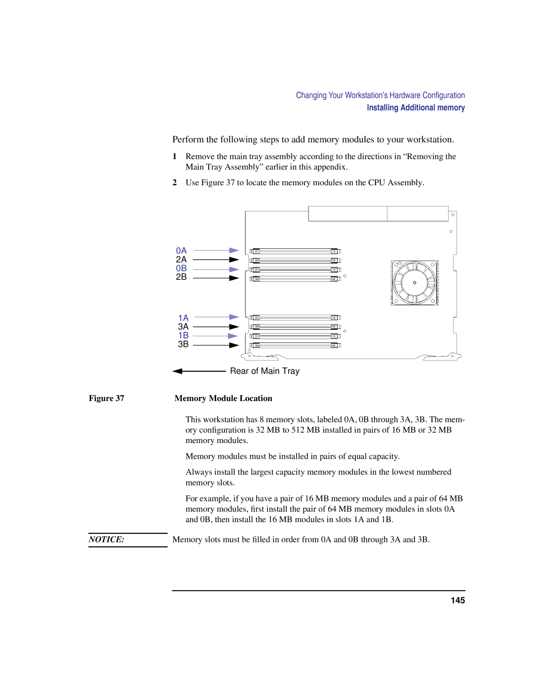
Memory Module Location
Installing Memory Cards
EISA/GSC Slots from Outside the System Unit
Installing an Eisa or GSC Option Board
Graphics Paths
Removing the Eisa Retainer
Installing the Option Board
Rotating the Fan
Removing the Eisa Slider and Blank Plate
Installing an Option Board
Installing the Eisa Retainer and Eisa Slider
Securing the Fan
Removing the Battery
Replacing the Battery
Changing Your Monitor Type
Setting the Monitor Type from the Boot Console Interface
Setting the Monitor Type at Power On
156
Scsi Connections
158
Fast, Wide Differential
Scsi Bus Differences
Address 7 is reserved for host controller use on both buses
Priority Address Bus
Cables
Scsi Restrictions
Scsi Configuration Constraints
Connectors and Terminators
Use the following cables
Following cables
Fast, Wide Differential Scsi Bus Configuration Constraints
Single-Ended SCSI-2 Bus Configuration Constraints
Single-Ended SCSI-2 Bus Configuration Constraints
Maximum Number of SCSI-2 Devices
Fast, Wide Differential Scsi Bus Configuration Constraints
Single-Ended SCSI-2 Bus Length
Determining Scsi Bus Length
166
Fast, Wide Differential Scsi Bus Length
Assigning Scsi Device IDs
169
170
Single-Ended Standard System Scsi Device IDs
External Device Drives
Fast, Wide Differential Scsi IDs
System contains two 2 Scsi connectors
Connecting to the Scsi Ports
Rear Panel Scsi Connectors without Terminators
System Scsi Port Connection
174
Boot Console Interface
176
Boot Console Interface Features
178
179
To access the boot console interface, follow these steps
Accessing the Boot Console Interface
Booting Your Workstation
ISL hpux /SYSBCKUP for ISL hpux /stand/vmunix.prev for
Ctrl
Searching for Bootable Media
Where devicetype is one of the following
Resetting Your Workstation
Type Specification Format
Displaying and Setting Paths
Mnemonic Style Notation
186
Monitor Command
Displaying and Setting the Monitor Type
Correct usage for setting the graphics configuration is
Where valid graphicspath parameters are
This example, the graphics cards are configured as follows
Displaying the Current Monitor Configuration
This places you in the Configuration Menu. From here type
Monitor Information
Setting the Monitor Type
190
191
192
193
This places you in the Information Menu. From here type
Displaying the Current Memory Configuration
SMC
Sample Output
196
Following table appears
Displaying the Status of the Eisa Slots
Where state is on or off
Setting the Auto Boot and Auto Search Flags
Autosearch searches for devices in the following order
To enable fastboot, type the following at the prompt
Displaying and Setting the Fastboot Mode
To disable fastboot, type the following at the prompt
Address is for the system’s built-in LAN
Displaying the LAN Station Address
Displaying System Information
Displaying PIM Information
204
Glossary
Bootstrap service See boot
Glossary
207
208
Iconify See iconize
210
Mouse pointer See pointer
Option See command option
Scsi See Small Computer System In- terface
Root See superuser
System name See internet protocol address
Working directory See current work- ing directory
Utility See utility program
215
216
217
218
219
220
221
222
223
224
225
226
227
228
229
230
231
232
Index
Device files
Scsi ID,, 23 Scsi ports
Title bar,, 214 transceiver