11.Replace the computer access panel.
12.If the computer was on a stand, replace the stand.
13.Reconnect the power cord and turn on the computer.
14.Lock any security devices that were disengaged when the access panel was removed.
15.Reconfigure the computer, if necessary.
System Board Connections
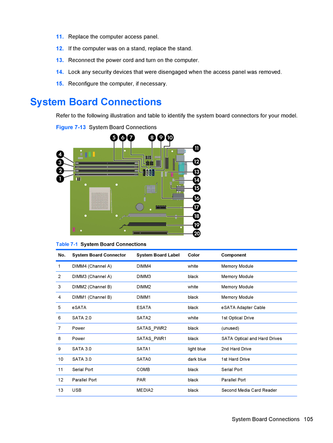
Refer to the following illustration and table to identify the system board connectors for your model. Figure
Table 7-1 System Board Connections
No. | System Board Connector | System Board Label | Color | Component |
|
|
|
|
|
1 | DIMM4 (Channel A) | DIMM4 | white | Memory Module |
|
|
|
|
|
2 | DIMM3 (Channel A) | DIMM3 | black | Memory Module |
|
|
|
|
|
3 | DIMM2 (Channel B) | DIMM2 | white | Memory Module |
|
|
|
|
|
4 | DIMM1 (Channel B) | DIMM1 | black | Memory Module |
|
|
|
|
|
5 | eSATA | ESATA | black | eSATA Adapter Cable |
|
|
|
|
|
6 | SATA 2.0 | SATA2 | white | 1st Optical Drive |
|
|
|
|
|
7 | Power | SATAS_PWR2 | black | (unused) |
|
|
|
|
|
8 | Power | SATAS_PWR1 | black | SATA Optical and Hard Drives |
|
|
|
|
|
9 | SATA 3.0 | SATA1 | light blue | 2nd Hard Drive |
|
|
|
|
|
10 | SATA 3.0 | SATA0 | dark blue | 1st Hard Drive |
|
|
|
|
|
11 | Serial Port | COMB | black | Serial Port |
|
|
|
|
|
12 | Parallel Port | PAR | black | Parallel Port |
|
|
|
|
|
13 | USB | MEDIA2 | black | Second Media Card Reader |
|
|
|
|
|
System Board Connections 105