Troubleshooting
Using the System Board LEDs for Troubleshooting
Table 2-2. Interpreting the System Board LEDs
LED Name | LED’s Color | Description |
| When On |
|
|
|
|
VRM0 | Green | This light, when on, indicates that the |
|
| voltage regulator module is working |
|
| correctly for processor zero. The |
|
| default state for this light is on. |
|
|
|
FETCH | Green | This light, when on, indicates that one |
|
| or both processors is fetching code. The |
|
| default state for this light is on. |
|
|
|
FANS | Yellow | Note that the yellow light blinks a |
| (blinking) | heart beat when the system is working |
|
| correctly. See Table |
|
| details for interpreting the blinks of |
|
| this light. |
|
|
|
Over Current | Red | This light, when on, indicates there is |
|
| a short somewhere in the system. The |
|
| default state for this light is off. |
|
|
|
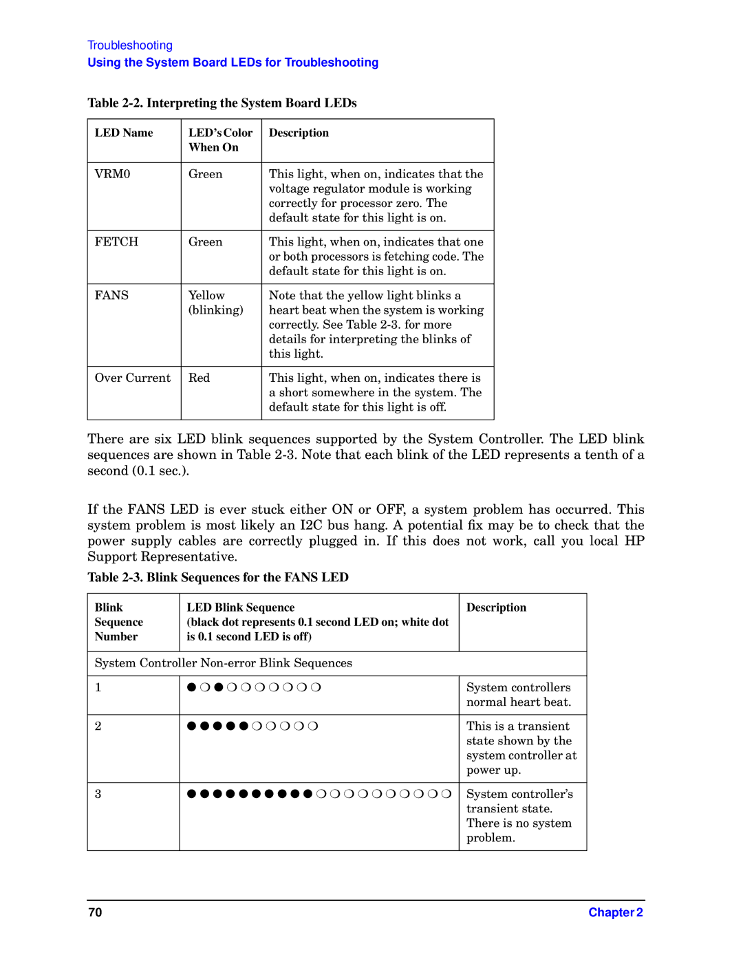
There are six LED blink sequences supported by the System Controller. The LED blink sequences are shown in Table
If the FANS LED is ever stuck either ON or OFF, a system problem has occurred. This system problem is most likely an I2C bus hang. A potential fix may be to check that the power supply cables are correctly plugged in. If this does not work, call you local HP Support Representative.
Table 2-3. Blink Sequences for the FANS LED
Blink | LED Blink Sequence | Description |
Sequence | (black dot represents 0.1 second LED on; white dot |
|
Number | is 0.1 second LED is off) |
|
|
|
|
System Controller |
| |
|
|
|
1 | ● ❍ ● ❍ ❍ ❍ ❍ ❍ ❍ ❍ | System controllers |
|
| normal heart beat. |
|
|
|
2 | ● ● ● ● ● ❍ ❍ ❍ ❍ ❍ | This is a transient |
|
| state shown by the |
|
| system controller at |
|
| power up. |
|
|
|
3 | ● ● ● ● ● ● ● ● ● ● ❍ ❍ ❍ ❍ ❍ ❍ ❍ ❍ ❍ ❍ | System controller’s |
|
| transient state. |
|
| There is no system |
|
| problem. |
|
|
|
70 | Chapter 2 |
