Types 2193, 2194,
Personal Computer
Page
Second Edition April
Page
Contents
Power management features
Vii
Bios Setup configuration
Adding and replacing system board components
Adding and removing adapter cards and drives
Appendix B. Modem information
Part 6. Technical reference Appendix A. Specification tables
Index
Appendix C. Monitor terminology Appendix D. Warranty
Page
Conventions used in this book
Symbols
Highlighting
Highlight Purpose
Installation
Safety information
Xiii
To avoid shock hazard
Safety while working with hardware
Disconnecting your computer
Regulatory safety notice for the CD-ROM and DVD-ROM drive
Lithium battery notice
Xvii
Laser compliance statement
Consignes de sécurité
Installation
Xix
Consignes de sécurité lors de la manipulation du matériel
Consignes de sécurité relatives au modem
Consignes de sécurité pour l’unité de CD-ROM et de DVD-ROM
Consignes relatives à la pile au lithium
Xxi
Conformité aux normes relatives aux appareils laser
North American FCC and telephone company requirements
Regulatory notices
Xxiii
Canadian Department of Communications certification label
Xxv
IBM Personal Computer machine types 2196, 2197,
Trademarks
European Community Directive Conformance Statement
Xxvii
Product
Year 2000 Notice Information
Xxix
Page
Arranging a comfortable and productive work area
Ergonomics
Arranging your work area
Xxxi
Positioning the monitor
Choosing a chair
Positioning the keyboard
Xxxiii
Positioning the mouse
Xxxiv IBM Personal Computer User Guide
Part 1. Learning about this book
Using this book on
Page
Using this book
Using this book
How this book is organized
2IBM Personal Computer User Guide
Part 3 Controlling system settings
Part 5 Troubleshooting
4IBM Personal Computer User Guide
Where to find more information
Express Maintenance on
HelpWare support and services on
Part 2. Support information
Page
What is IBM HelpWare?
HelpWare support and services
HelpWare support and services
What do I do first?
Printed documentation
What can I do on my own?
Online documentation
Software
Diagnostics
Electronic support
How do I get help electronically?
Internet
What help can I get by telephone?
How and when do I contact the IBM PC HelpCenter?
Day Up and Running support
Software technical support
Hardware warranty service
Additional support
6IBM Personal Computer User Guide
Before you call
8IBM Personal Computer User Guide
Purchasing additional HelpWare services
How and when do I purchase additional support?
You can purchase support in the following ways
10IBM Personal Computer User Guide
Flat rate
To order additional support packages
International Warranty Service Not Available
12IBM Personal Computer User Guide
Express Maintenance
Express Maintenance
2IBM Personal Computer User Guide
Power management features on
Part 3. Controlling system settings
Bios Setup configuration on
Getting started on
Page
Getting started
Getting started
Getting the best performance from your monitor
Controlling monitor settings
Changing display settings
Power saver feature
Customizing display properties
Tips for choosing display properties
Monitor
Using the Windows Help function to select display properties
Adjusting the speaker volume
Controlling volume
Adjusting the headphone volume
8IBM Personal Computer User Guide
Getting ready to print
Connecting your modem to the telephone network
Setting up communications
Configuring your communications software
IBM Internet Connection Services
Configuring your computer for a connection to the Internet
Microsoft Network
Internet Connection Wizard
Using the Rapid Access II keyboard
Click on the Internet Connection Wizard option
14IBM Personal Computer User Guide
Power management features
Power management features
Software shutdown
Using the software shutdown feature
Using the power button
Using the Windows 98 Start menu
System Standby
When the system is in normal on state
Using the Power Management feature in Windows
Monitor standby
Bios Setup configuration
Bios Setup configuration
Configuration/Setup Utility overview
Bios Setup configuration
When the computer is on
Entering Setup
When the computer is off
Configuration/Setup Utility menu
Working with the Setup menus
F10 Enter Esc
Viewing system information and product data
Loading the default settings
Changing parameter settings
Exiting Setup
Canceling changes
Devices and I/O Ports
Setup parameters
IDE drives setup
USB Setup
PS/2 Mouse Detect Function
Video Setup
Start Options
Boot Up Floppy Seek
Quick Power-On Self Test
Boot Up NumLock Status
Gate A20 Option
Typematic Rate Setting
Typematic Rate Chars/Sec
Halt On
Typematic Delay Msec
Date and Time
Power Management Setup
Advanced Setup
Cache Control
ROM Shadowing
Activity Monitor
Video Off Method
18IBM Personal Computer User Guide
Set Password
Clock Generator Configuration
Automatic Power On
Acpi suspend Type
20IBM Personal Computer User Guide
Using other configuration utilities
22IBM Personal Computer User Guide
Part 4. Upgrading and replacing hardware
Preparing to upgrade on
Page
Preparing to upgrade
Preparing to upgrade
For conflicts with system resources used by adapter cards
Evaluating your new hardware
For conflicts with other system resources
Recording your changes
Planning your hardware changes
Using the Windows 98 Device Manager
Using Setup
Resolving resource conflicts
Opening the system unit
Taking safety precautions
Removing the top cover
6IBM Personal Computer User Guide
Looking inside the system unit
8IBM Personal Computer User Guide
Adding and removing adapter cards and drives
Adding and removing adapter cards and drives
Setting modem card configurations
Resolving conflicts with installed adapter cards
Click on View devices by type
Working with the hardware in the system unit
Adding and removing adapter cards
Installing adapter cards
Removing adapter cards
Removing and adding drives
Identifying signal cable connectors
Guidelines for connecting IDE/ATA signal cables
8IBM Personal Computer User Guide
Guidelines for connecting diskette interface signal cables
Removing the diskette drive
Removing the CD-ROM drive
Removing the hard disk drive
Installing a drive in Bay
14IBM Personal Computer User Guide
For adapter cards
Updating the Cmos settings in Setup
For Drives
16IBM Personal Computer User Guide
Adding and replacing system board components
Adding and replacing system board components
Identifying system board parts machine type
Processor FAN, processor and heat sink U5
Locating system board jumpers and connectors machine type
Identifying system board parts machine type 2194
Processor FAN, processor and heat sink J1
Adding and replacing system board components
Identifying adapter card connectors
Card connector and jumper information
Setting a jumper
Upgrading the system memory
Installing memory modules
Verifying the system memory
Removing memory modules
Replacing the system battery
12IBM Personal Computer User Guide
Updating the Cmos settings in Setup
14IBM Personal Computer User Guide
Diagnosing and recovering from problems on
Part 5. Troubleshooting
Page
Diagnosing and recovering from problems
Diagnosing and recovering from problems
10-2IBM Personal Computer User Guide
Before you panic some simple fixes
Yes
Dram
Yes, more than once
Is anything displayed on the monitor?
10-4IBM Personal Computer User Guide
Step Is anything displayed on the monitor?
10-6IBM Personal Computer User Guide
Quick problem solving chart
Solving hardware problems
Solving hardware and software problems
Hardware problems
10-8IBM Personal Computer User Guide
Diagnosing and recovering from problems
10-10IBM Personal Computer User Guide
Insert the Recovery and Diagnostics CD-ROM into
10-12IBM Personal Computer User Guide
Software problems
Solving software problems
10-14IBM Personal Computer User Guide
Modem problems
Solving modem problems
10-16IBM Personal Computer User Guide
Error codes and messages
Error codes and messages
10-18IBM Personal Computer User Guide
1783
Starting PC-Doctor for Windows
IBM Diagnostic Programs
10-20IBM Personal Computer User Guide
Select PC-Doctor for Windows Click PC-Doctor for Windows
Reinstalling device drivers
Starting the IBM Enhanced Diagnostics program
10-22IBM Personal Computer User Guide
Recovering factory-installed programs and files
Diagnosing and recovering from problems
10-24IBM Personal Computer User Guide
Appendix D. Warranty on page D-1
Appendix A. Specification tables on page A-1
Part 6. Technical reference
Appendix B. Modem information on page B-1
Page
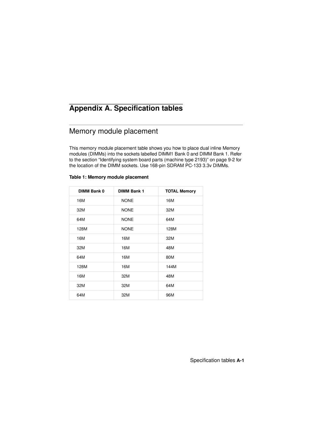
Memory module placement
Appendix A. Specification tables
Specification tables A-1
Memory module placement
2IBM Personal Computer User Guide
Memory map
Specification tables A-3
Memory map
System input/output addresses
System input/output addresses
Specification tables A-5
System interrupts
System interrupts
DMA channel assignments
Specification tables A-7
DMA channel assignments
Serial port addresses
Serial port addresses
Specification tables A-9
Connector functions
Connector functions
10IBM Personal Computer User Guide
Specification tables A-11
KBMS1
Appendix B. Modem information
Modem features
Modem information B-1
2IBM Personal Computer User Guide
Operating your modem
Using the Auto Answer feature
Modem information B-3
# or *70,,,complete telephone number
Disabling Call Waiting
Executing commands
Modem commands
Command format
Modem information B-5
AT commands
AT commands
Sr=n
Modem information B-7
8IBM Personal Computer User Guide
Modem information B-9
Detail for +MS Controls
Detail for +MS Controls
Extended AT commands
Extended AT commands
42bis commands
42bis commands
Modem information B-11
Basic Response codes
Modem response codes
Modem information B-13
Registers
To read the value of an S register
To change the value of an S register
Registers
Register Function Range/units Default
Monitor terminology C-1
Appendix C. Monitor terminology
Monitor terms and definitions
2IBM Personal Computer User Guide
Warranty statements
Appendix D. Warranty
Warranty D-1
2IBM Personal Computer User Guide
Warranties of ANY Kind
Warranty D-3
4IBM Personal Computer User Guide
Warranty D-5
6IBM Personal Computer User Guide
Warranty D-7
8IBM Personal Computer User Guide
Warranty D-9
Asia Pacific
Part 2 Country-Unique Terms
EUROPE, Middle EAST, Africa Emea
Warranty D-11
Following terms apply to the country specified
Warranty D-13
North America
Index
Index
Simple fixes 10-2 software problems
Index
Index