Design Guide Checklist
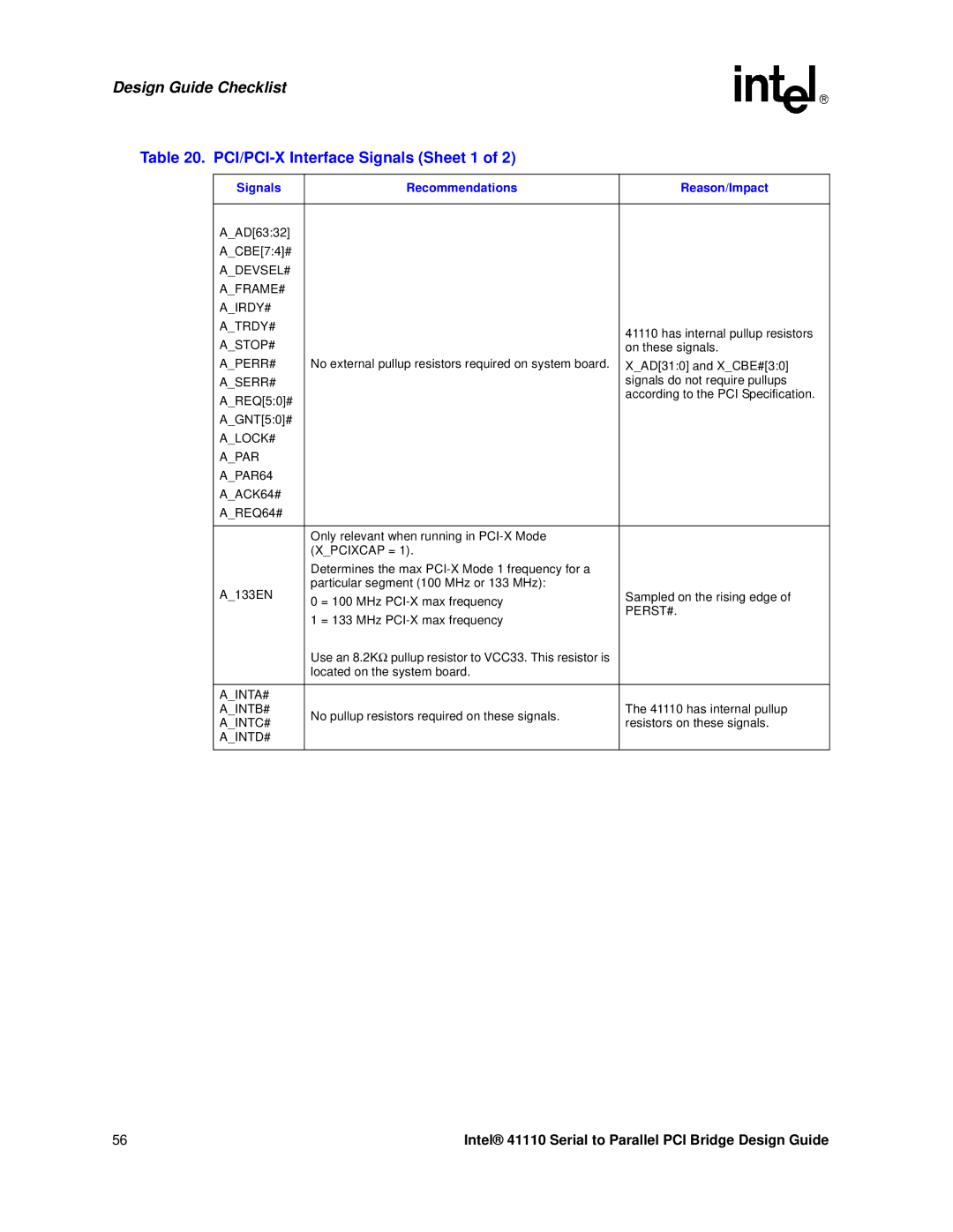
Table 20. PCI/PCI-X Interface Signals (Sheet 1 of 2)
Signals | Recommendations | Reason/Impact | |
|
|
| |
A_AD[63:32] |
|
| |
A_CBE[7:4]# |
|
| |
A_DEVSEL# |
|
| |
A_FRAME# |
|
| |
A_IRDY# |
|
| |
A_TRDY# |
| 41110 has internal pullup resistors | |
A_STOP# |
| ||
| on these signals. | ||
A_PERR# | No external pullup resistors required on system board. | X_AD[31:0] and X_CBE#[3:0] | |
A_SERR# |
| signals do not require pullups | |
A_REQ[5:0]# |
| according to the PCI Specification. | |
|
| ||
A_GNT[5:0]# |
|
| |
A_LOCK# |
|
| |
A_PAR |
|
| |
A_PAR64 |
|
| |
A_ACK64# |
|
| |
A_REQ64# |
|
| |
|
|
| |
| Only relevant when running in |
| |
| (X_PCIXCAP = 1). |
| |
| Determines the max |
| |
A_133EN | particular segment (100 MHz or 133 MHz): | Sampled on the rising edge of | |
0 = 100 MHz | |||
| PERST#. | ||
| 1 = 133 MHz | ||
|
| ||
| Use an 8.2KΩ pullup resistor to VCC33. This resistor is |
| |
| located on the system board. |
| |
|
|
| |
A_INTA# |
|
| |
A_INTB# | No pullup resistors required on these signals. | The 41110 has internal pullup | |
A_INTC# | resistors on these signals. | ||
| |||
A_INTD# |
|
| |
|
|
|
56 | Intel® 41110 Serial to Parallel PCI Bridge Design Guide |