|
|
| Design Guide Checklist |
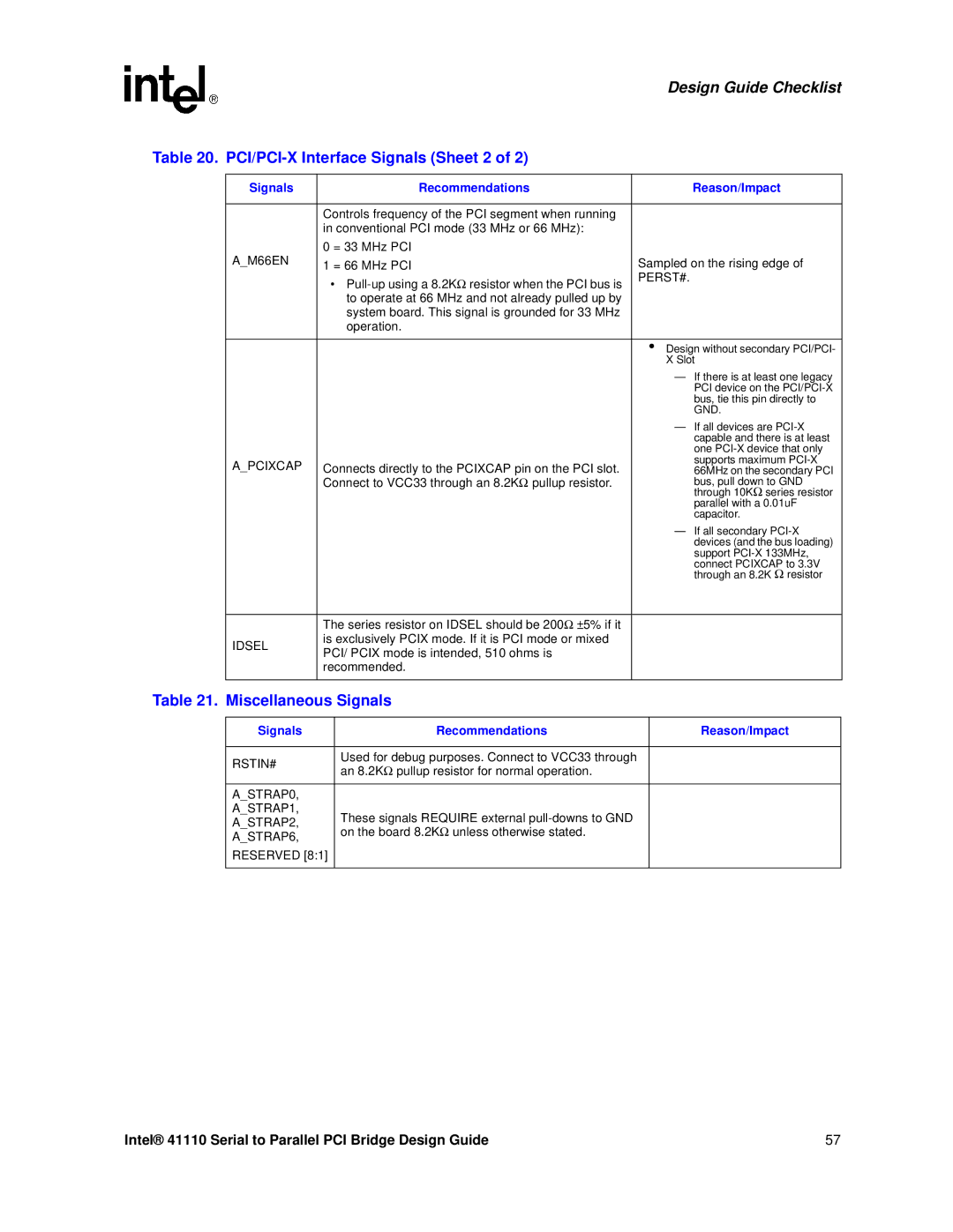
Table 20. |
| ||
|
|
|
|
| Signals | Recommendations | Reason/Impact |
|
|
|
|
|
| Controls frequency of the PCI segment when running |
|
|
| in conventional PCI mode (33 MHz or 66 MHz): |
|
| A_M66EN | 0 = 33 MHz PCI |
|
| 1 = 66 MHz PCI | Sampled on the rising edge of | |
|
| • | PERST#. |
|
|
| |
|
| to operate at 66 MHz and not already pulled up by |
|
|
| system board. This signal is grounded for 33 MHz |
|
|
| operation. |
|
|
|
|
|
|
|
| • Design without secondary PCI/PCI- |
|
|
| X Slot |
|
|
| — If there is at least one legacy |
|
|
| PCI device on the |
|
|
| bus, tie this pin directly to |
|
|
| GND. |
|
|
| — If all devices are |
|
|
| capable and there is at least |
|
|
| one |
| A_PCIXCAP | Connects directly to the PCIXCAP pin on the PCI slot. | supports maximum |
| 66MHz on the secondary PCI | ||
|
| Ω | bus, pull down to GND |
|
| Connect to VCC33 through an 8.2K pullup resistor. | through 10KΩ series resistor |
|
|
| parallel with a 0.01uF |
|
|
| capacitor. |
|
|
| — If all secondary |
|
|
| devices (and the bus loading) |
|
|
| support |
|
|
| connect PCIXCAP to 3.3V |
|
|
| through an 8.2K Ω resistor |
|
|
|
|
|
| The series resistor on IDSEL should be 200Ω ±5% if it |
|
| IDSEL | is exclusively PCIX mode. If it is PCI mode or mixed |
|
| PCI/ PCIX mode is intended, 510 ohms is |
| |
|
|
| |
|
| recommended. |
|
|
|
|
|
Table 21. Miscellaneous Signals
Signals | Recommendations | Reason/Impact |
|
|
|
RSTIN# | Used for debug purposes. Connect to VCC33 through |
|
an 8.2KΩ pullup resistor for normal operation. |
| |
|
| |
|
|
|
A_STRAP0, |
|
|
A_STRAP1, | These signals REQUIRE external |
|
A_STRAP2, |
| |
on the board 8.2KΩ unless otherwise stated. |
| |
A_STRAP6, |
| |
|
| |
RESERVED [8:1] |
|
|
|
|
|
Intel® 41110 Serial to Parallel PCI Bridge Design Guide | 57 |
