PCI-X Layout Guidelines
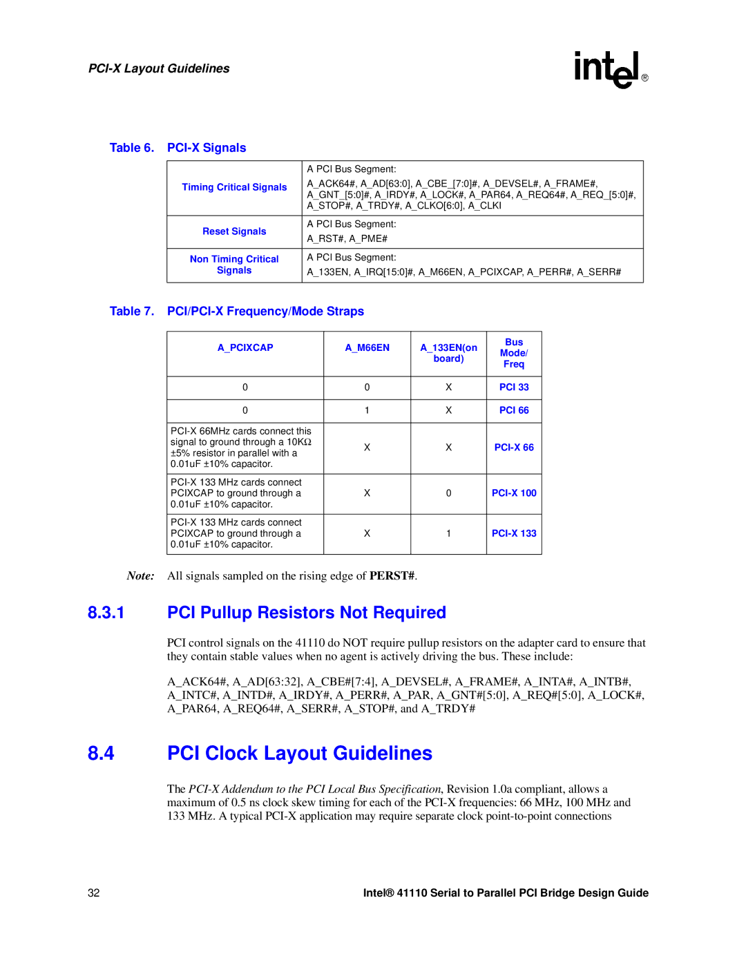
Table 6. PCI-X Signals
| A PCI Bus Segment: | |
Timing Critical Signals | A_ACK64#, A_AD[63:0], A_CBE_[7:0]#, A_DEVSEL#, A_FRAME#, | |
A_GNT_[5:0]#, A_IRDY#, A_LOCK#, A_PAR64, A_REQ64#, A_REQ_[5:0]#, | ||
| ||
| A_STOP#, A_TRDY#, A_CLKO[6:0], A_CLKI | |
|
| |
Reset Signals | A PCI Bus Segment: | |
A_RST#, A_PME# | ||
| ||
|
| |
Non Timing Critical | A PCI Bus Segment: | |
Signals | A_133EN, A_IRQ[15:0]#, A_M66EN, A_PCIXCAP, A_PERR#, A_SERR# | |
|
|
Table 7. PCI/PCI-X Frequency/Mode Straps
A_PCIXCAP | A_M66EN | A_133EN(on | Bus | |
Mode/ | ||||
|
| board) | ||
|
| Freq | ||
|
|
| ||
|
|
|
| |
0 | 0 | X | PCI 33 | |
|
|
|
| |
0 | 1 | X | PCI 66 | |
|
|
|
| |
|
|
| ||
signal to ground through a 10KΩ | X | X | ||
±5% resistor in parallel with a | ||||
|
|
| ||
0.01uF ±10% capacitor. |
|
|
| |
|
|
|
| |
|
| |||
PCIXCAP to ground through a | X | 0 | ||
0.01uF ±10% capacitor. |
|
|
| |
|
|
|
| |
|
| |||
PCIXCAP to ground through a | X | 1 | ||
0.01uF ±10% capacitor. |
|
|
| |
|
|
|
|
Note: All signals sampled on the rising edge of PERST#.
8.3.1PCI Pullup Resistors Not Required
PCI control signals on the 41110 do NOT require pullup resistors on the adapter card to ensure that they contain stable values when no agent is actively driving the bus. These include:
A_ACK64#, A_AD[63:32], A_CBE#[7:4], A_DEVSEL#, A_FRAME#, A_INTA#, A_INTB#, A_INTC#, A_INTD#, A_IRDY#, A_PERR#, A_PAR, A_GNT#[5:0], A_REQ#[5:0], A_LOCK#, A_PAR64, A_REQ64#, A_SERR#, A_STOP#, and A_TRDY#
8.4PCI Clock Layout Guidelines
The
32 | Intel® 41110 Serial to Parallel PCI Bridge Design Guide |