Intel® IQ80321 I/O Processor Evaluation Platform
Hardware Reference Section
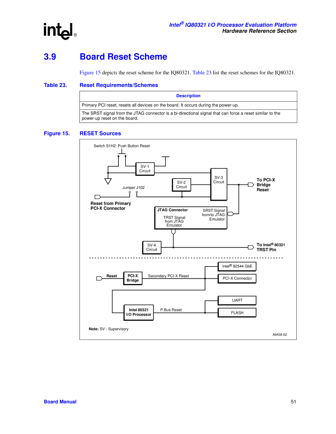
3.9Board Reset Scheme
Figure 15 depicts the reset scheme for the IQ80321. Table 23 list the reset schemes for the IQ80321.
Table 23. Reset Requirements/Schemes
Description
Primary PCI reset, resets all devices on the board. It occurs during the
The SRST signal from the JTAG connector is a
Figure 15. | RESET Sources |
|
|
|
|
|
| Switch S1H2: Push Button Reset |
|
|
| ||
|
|
|
|
|
| |
|
|
| Circuit |
|
|
|
|
|
|
|
| To | |
|
|
|
| Circuit | ||
|
|
|
| Bridge | ||
|
| Jumper J102 | Circuit |
| ||
|
|
| Reset | |||
|
|
|
|
|
| |
| Reset from Primary |
|
|
|
| |
|
|
| JTAG Connector | SRST Signal |
| |
|
|
|
|
| ||
|
|
|
| TRST Signal | from/to JTAG |
|
|
|
|
| Emulator |
| |
|
|
|
| from JTAG |
| |
|
|
|
|
|
| |
|
|
|
| Emulator |
|
|
|
|
|
|
| To Intel® 80321 | |
|
|
| Circuit |
|
| TRST Pin |
|
|
|
|
| Intel® 82544 GbE |
|
| Reset | Secondary |
| |||
|
| Bridge |
|
|
| |
|
|
|
|
|
| |
|
|
|
|
| UART |
|
|
| Intel 80321 | FLASH |
| ||
|
| I/O Processor |
|
| ||
|
|
|
|
| ||
| Note: SV - Supervisory |
|
|
|
| |
|
|
|
|
|
| |
Board Manual |
|
|
|
|
| 51 |