Operation
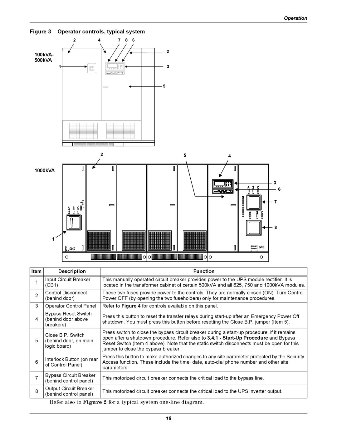
Figure 3 Operator controls, typical system |
|
|
100kVA- |
|
|
500kVA |
|
|
2 | 5 | 4 |
1000kVA |
|
|
3
6
7
8
1
Item | Description | Function | |
1 | Input Circuit Breaker | This manually operated circuit breaker provides power to the UPS module rectifier. It is | |
(CB1) | located in the transformer cabinet of certain 500kVA and all 625, 750 and 1000kVA modules. | ||
| |||
2 | Control Disconnect | These two fuses provide power to the controls. They are normally closed (ON). Turn Control | |
(behind door) | Power OFF (by opening the two fuseholders) only for maintenance procedures. | ||
| |||
3 | Operator Control Panel | Refer to Figure 4 for controls available on this panel. | |
| Bypass Reset Switch | Press this button to reset the transfer relays during | |
4 | (behind door above | ||
shutdown. You must press this button before resetting the Close B.P. jumper (Item 5). | |||
| breakers) | ||
|
| ||
|
|
| |
| Close B.P. Switch | Press switch to close the bypass circuit breaker during a | |
| open after a shutdown procedure. Refer also to 3.4.1 - | ||
5 | (behind door, on main | ||
Reset Switch (Item 4 above). Note that the static switch disconnects must be open for this | |||
| logic board) | ||
| jumper to close the bypass breaker. | ||
|
| ||
|
|
| |
| Interlock Button (on rear | Press this button to make authorized changes to any site parameter protected by the Security | |
6 | Access function. These include the time, date, | ||
| of Control Panel) | parameters. | |
|
| ||
|
|
| |
7 | Bypass Circuit Breaker | This motorized circuit breaker connects the critical load to the bypass line. | |
(behind control panel) | |||
|
| ||
8 | Output Circuit Breaker | This motorized circuit breaker connects the critical load to the UPS inverter output. | |
(behind control panel) | |||
|
|
Refer also to Figure 2 for a typical system one-line diagram.
18