Operation
3.4.2Load Transfer Procedures
Use the Monitor/Mimic Display to determine the operating condition of the UPS module. Press the Alarm Reset pad to clear the Alarm Messages. Refer to Table 4 for an explanation of any remaining alarm messages (except Load On Bypass). Call Liebert Global Services if you cannot clear the remain- ing alarm messages.
If the only alarm message displayed is Load On Bypass (or no alarms), you can perform a manual transfer of the load between the UPS module and the UPS bypass line. Changing the load from the UPS system to the UPS bypass is called a transfer. Changing the load from UPS bypass to the UPS system is called a retransfer. Note that the UPS system control logic can initiate automatic load transfers and retransfers. Refer to 3.5 - Automatic Operations.
STEP 1 (Load Transfer Procedures)
a.Press the Select pad to display the Master Menu on the LCD. Move the highlighted cursor to Load Transfer Procedures (using the Up and Down pads). Press the Select pad to display the Load Transfer Procedures screen.
b.Verify that the OK TO TRANSFER message is highlighted. If not (if the TRANSFER PROHIBIT message is highlighted instead), slowly rotate the Voltage Adjust knob (see Figure 4) to match the UPS system voltage to the bypass voltage.
NOTE
1. UPS output voltage changes VERY slowly in response to movements of the Voltage Adjust knob. To avoid overshooting, allow at least a minute for UPS output voltage to stabilize before proceeding to the next step.
2.If the TRANSFER PROHIBIT message remains, refer to Table 4 for corrective action for any alarm messages. Call Liebert Global Services if you cannot solve the problem.
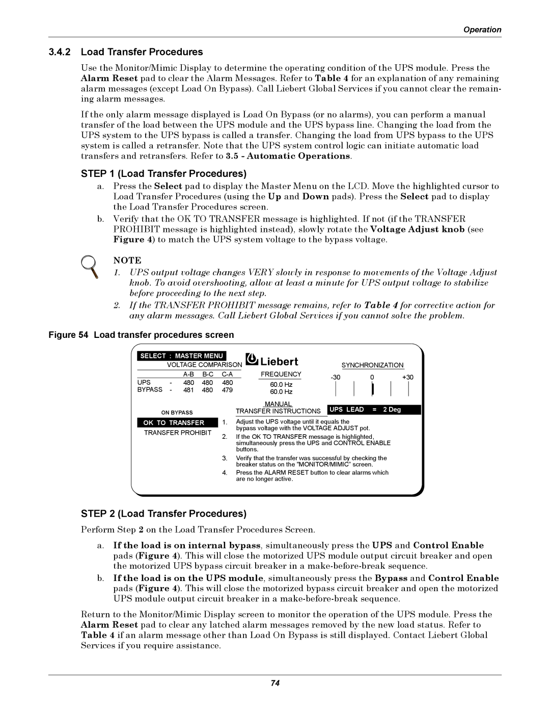
Figure 54 Load transfer procedures screen
SELECT : MASTER MENU |
|
|
|
|
|
|
|
|
|
|
| ||||
| VOLTAGE COMPARISON |
|
|
|
| SYNCHRONIZATION | |||||||||
|
|
| FREQUENCY | 0 | +30 | ||||||||||
UPS | - | 480 | 480 | 480 |
|
|
| ||||||||
| 60.0 Hz | ||||||||||||||
|
|
|
|
|
|
|
| ||||||||
BYPASS | - | 481 | 480 | 479 |
| 60.0 Hz |
|
|
|
|
|
|
| ||
|
|
|
|
|
|
|
| ||||||||
ON BYPASS
OK TO TRANSFER
TRANSFER PROHIBIT
MANUAL | UPS LEAD = 2 Deg |
TRANSFER INSTRUCTIONS |
1.AdjustthetheUPSvoltageuntilitl itequalsthethe bypassvoltagevoltagewithwiththetheVOLTAGEVOLTAGEADJUSTADJUSTpotpot. .
2.IfIftheOKTOTRANSFERmessageisishighlighted, simultaneouslypressthetheUPSBYPASSand CONTROLand CONTROLENABLENABLE buttons.
buttons.
3.Verifythatthetransferwawassuccessfulbybycheckingthethe breakerstatusstatusononthethe"MONITOR/MIMIC”MIC"screenscreen. .
4.PressstheALARMRESETbuttontotoclearclearalalarmswhichwhich arearenonolongeractive.
STEP 2 (Load Transfer Procedures)
Perform Step 2 on the Load Transfer Procedures Screen.
a.If the load is on internal bypass, simultaneously press the UPS and Control Enable pads (Figure 4). This will close the motorized UPS module output circuit breaker and open the motorized UPS bypass circuit breaker in a
b.If the load is on the UPS module, simultaneously press the Bypass and Control Enable pads (Figure 4). This will close the motorized bypass circuit breaker and open the motorized UPS module output circuit breaker in a
Return to the Monitor/Mimic Display screen to monitor the operation of the UPS module. Press the Alarm Reset pad to clear any latched alarm messages removed by the new load status. Refer to Table 4 if an alarm message other than Load On Bypass is still displayed. Contact Liebert Global Services if you require assistance.
74