Operation
3.2.8Start-Up Procedures Screen
From the Master Menu, move the highlighted cursor to
This
Prior to this procedure, supply power to the critical load through the bypass line.
Refer to 3.4.1 - Start-Up Procedure for more details.
NOTE
If the system was shut down in response to an “Emergency Off” signal (typically because of a load fault), there may be alarm messages on the LCD screen that describe system conditions before (or at the time of) the shutdown. Some or all of the alarm conditions may have already been resolved. To clear these alarm messages, make sure the critical load is on bypass power and turn off the control power (see Figures 3 and 4). Wait at least ten minutes for the control power circuitry to completely
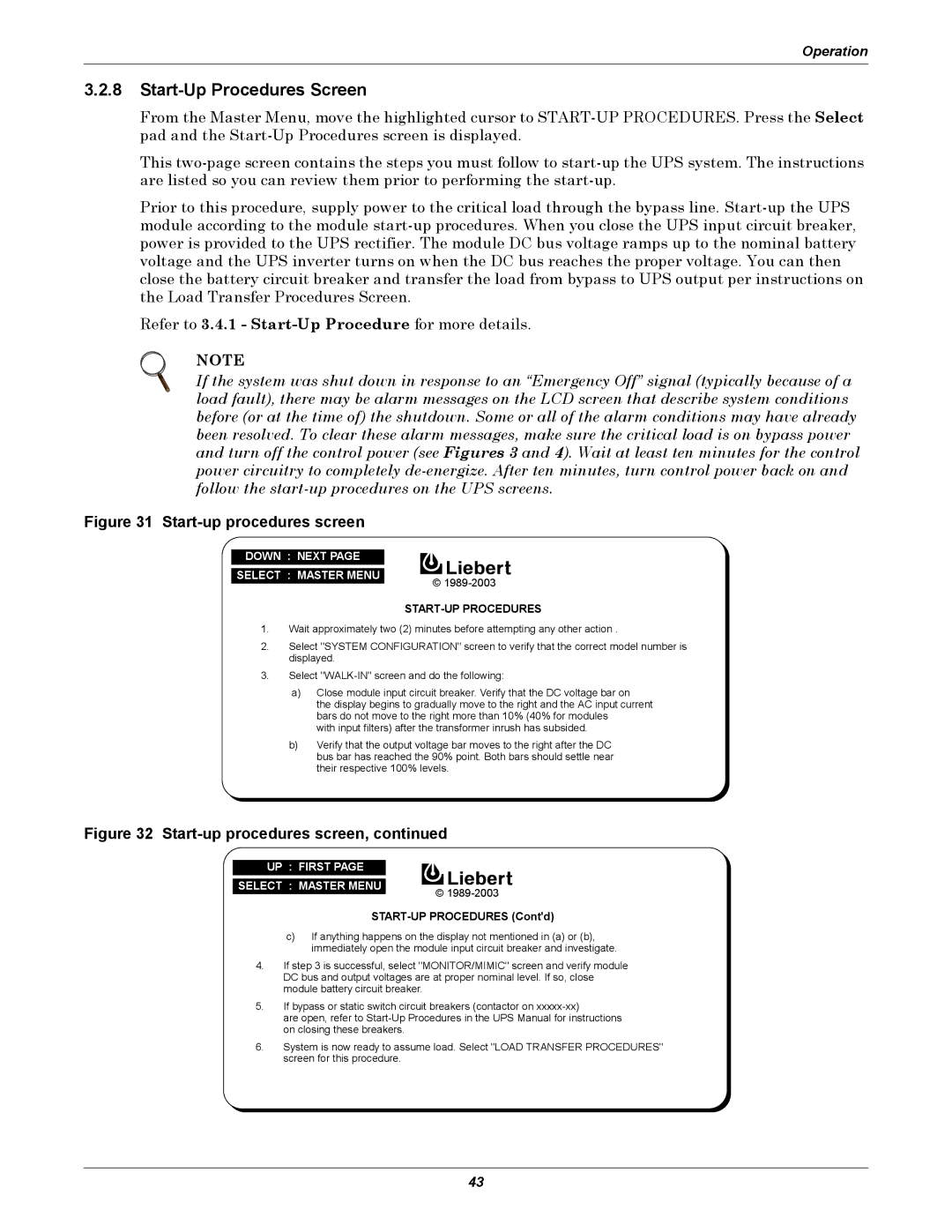
Figure 31 Start-up procedures screen
DOWN : NEXT PAGE
SELECT : MASTER MENU
©
START-UP PROCEDURES
1.Wait approximately two (2) minutes before attempting any other action .
2.Select "SYSTEM CONFIGURATION" screen to verify that the correct model number is displayed.
3.Select
a)Close module input circuit breaker. Verify that the DC voltage bar on
the display begins to gradually move to the right and the AC input current bars do not move to the right more than 10% (40% for modules
with input filters) after the transformer inrush has subsided.
b)Verify that the output voltage bar moves to the right after the DC bus bar has reached the 90% point. Both bars should settle near their respective 100% levels.
Figure 32 Start-up procedures screen, continued
UP : FIRST PAGE
SELECT : MASTER MENU | © |
|
START-UP PROCEDURES (Cont'd)
c)If anything happens on the display not mentioned in (a) or (b), immediately open the module input circuit breaker and investigate.
4.If step 3 is successful, select "MONITOR/MIMIC" screen and verify module DC bus and output voltages are at proper nominal level. If so, close module battery circuit breaker.
5.If bypass or static switch circuit breakers (contactor on
are open, refer to
6.System is now ready to assume load. Select "LOAD TRANSFER PROCEDURES" screen for this procedure.
43