Operation
Figure 5 illustrates the primary screens that you can access through the Operator Interface Display System. The liquid crystal display (LCD) screen provides a full 80 characters by 25 lines of informa- tion for easy readability. The following sections describe what these screens display and how and when to use them.
System status information is available on the display screen and at local and remote terminals, pro- vided Control Power is ON, even when the UPS module is not operating.
The screen will automatically display the Monitor/Mimic during normal operation. The System con- figuration screen will be displayed during start-up and whenever a system reset is required.
If a module display screen is blank, either power is not available, the Rectifier Input (RIB) circuit breaker (external to the UPS module) is open or the Control Power switch is OFF. If power is avail- able and a display is blank, contact Liebert Global Services (1-800-LIEBERT). Note that status infor- mation may be available at local and remote terminals. Use control touch pads to manually transfer the critical load to the bypass line if the display goes blank while load is on UPS (a very unlikely event).
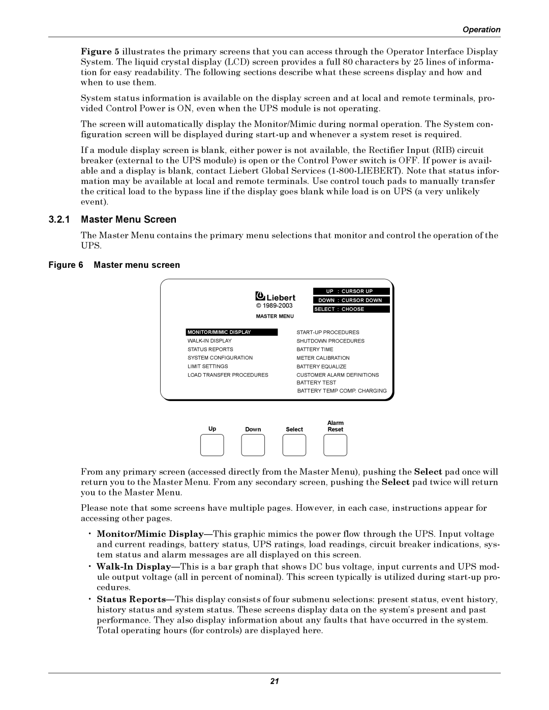
3.2.1Master Menu Screen
The Master Menu contains the primary menu selections that monitor and control the operation of the UPS.
Figure 6 Master menu screen
|
|
| UP : CURSOR UP |
|
|
|
|
| © | DOWN : CURSOR DOWN | |
|
| ||
| SELECT : CHOOSE | ||
|
|
| |
| MASTER MENU |
| |
|
| ||
MONITOR/MIMIC DISPLAY | |||
| SHUTDOWN PROCEDURES | ||
STATUS REPORTS |
| BATTERY TIME | |
SYSTEM CONFIGURATION | METER CALIBRATION | ||
LIMIT SETTINGS |
| BATTERY EQUALIZE | |
LOAD TRANSFER PROCEDURES | CUSTOMER ALARM DEFINITIONS | ||
|
| BATTERY TEST | |
|
| BATTERY TEMP COMP. CHARGING | |
Up |
|
| Alarm |
Down | Select | Reset | |
From any primary screen (accessed directly from the Master Menu), pushing the Select pad once will return you to the Master Menu. From any secondary screen, pushing the Select pad twice will return you to the Master Menu.
Please note that some screens have multiple pages. However, in each case, instructions appear for accessing other pages.
•Monitor/Mimic
•
•Status
21