Operation
3.2.2Monitor/Mimic Display Screen
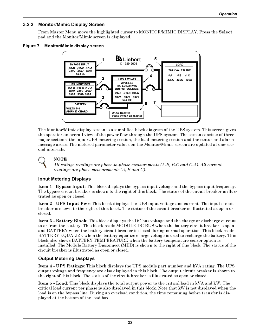
From Master Menu move the highlighted cursor to MONITOR/MIMIC DISPLAY. Press the Select pad and the Monitor/Mimic screen is displayed.
Figure 7 Monitor/Mimic display screen
|
| 1 | © | |||
BYPASS INPUT | ||||||
|
|
| ||||
480V | 480V | 480V |
|
|
| |
| 60.0 Hz | 2 |
|
| 4 | |
|
|
|
| |||
|
| UPS RATINGS | ||||
UPS INPUT PWR |
| |||||
RATED 500 KVA | ||||||
OUTPUT VOLTAGE | ||||||
480V | 480V | 480V | ||||
350A | 350A 350A | |||||
|
| 3 | 480V | 480V | 480V | |
|
|
|
| 60.0 Hz | 6 | |
BATTERY |
|
| ||||
5 |
|
|
| LOAD |
|
270 KVA / 217 KW | ||
A | B | C |
325A | 325A | 325A |
7 |
|
|
VOLTS 540 AMPS 15 CHARG
OK to Transfer
Static Switch Connected
The Monitor/Mimic display screen is a simplified block diagram of the UPS system. This screen gives the operator an overall view of the power flow through the UPS system. The screen consists of three major sections: the input/UPS metering section, the load metering section and the status and alarm message areas. The metered parameter values on the Monitor/Mimic screen are updated at
NOTE
All voltage readings are
Input Metering Displays
Item 1 - Bypass Input: This block displays the bypass input voltage and the bypass input frequency. The bypass circuit breaker is shown to the right of this block. The status of the circuit breaker is illus- trated as open or closed.
Item 2 - UPS Input Pwr: This block displays the UPS input voltage and current. The input circuit breaker is shown to the right of this block. The status of the circuit breaker is illustrated as open or closed.
Item 3 - Battery Block: This block displays the DC bus voltage and the charge or discharge current to or from the battery. This block reads MODULE DC BUS when the battery circuit breaker is open and BATTERY when the battery circuit breaker is closed during normal operation. This block reads BATTERY EQUALIZE when the battery equalize charge voltage is used to recharge the battery. This block also shows BATTERY TEMPERATURE when the battery temperature sensor option is installed. The Module Battery Disconnect (MBD) is shown to the right of this block. The status of the circuit breaker is illustrated as open or closed.
Output Metering Displays
Item 4 - UPS Ratings: This block displays the UPS module part number and kVA rating. The UPS output voltage and frequency are also displayed in this block. The output circuit breaker is shown to the right of this block. The status of the circuit breaker is illustrated as open or closed.
Item 5 - Load: This block displays the total output power to the critical load in kVA and kW. The critical load current per phase is also displayed in this block. Note that kW is not displayed when the load is on the bypass line. During an overload condition, the time remaining before transfer is dis- played at the bottom of the load box.
23