Operation
3.3Modes of Operation
This section illustrates the flow of power through circuit breakers, switches and UPS components dur- ing various modes of operation. The same modes of operation apply to all configurations of the Liebert Series 610 UPS. Highlighted (thick) lines in the diagrams indicate power flow and power availability.
These illustrations show a
These illustrations do not show an alternate power source (generator) and automatic transfer switch (external to the UPS) that might be present at your installation.
Table 7 below lists abbreviations for circuit breakers used in this manual.
Table 7 | Circuit breaker abbreviations | |
Abbreviation | Circuit Breaker | |
|
|
|
BFB |
| Bypass Feeder Breaker |
|
|
|
BIB |
| Bypass Input Breaker |
|
|
|
MBB |
| Maintenance Bypass Breaker |
|
|
|
MBD |
| Module Battery Disconnect |
|
|
|
MIB |
| Maintenance Isolation Breaker |
|
|
|
RIB |
| Rectifier Input Breaker |
|
|
|
3.3.1Load on Bypass
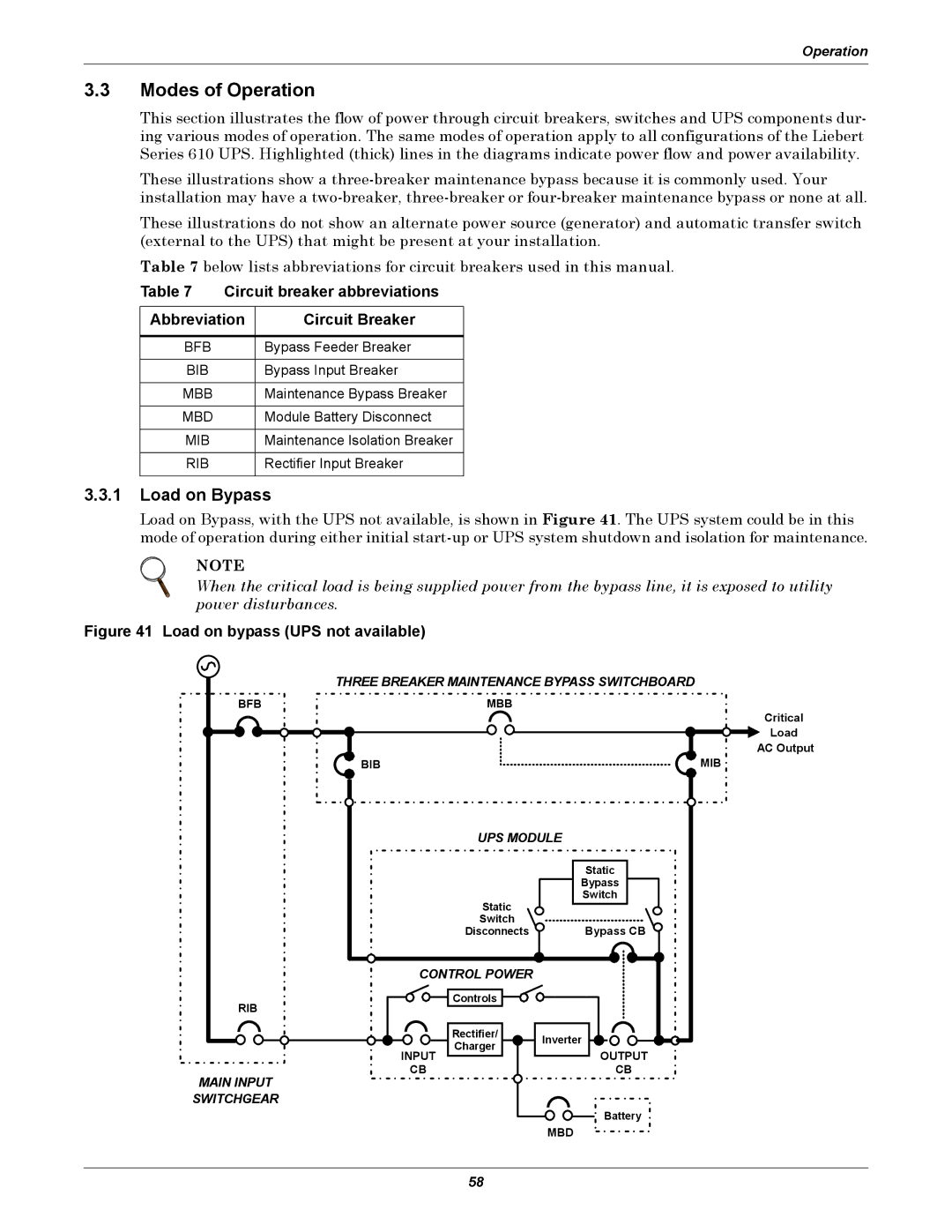
Load on Bypass, with the UPS not available, is shown in Figure 41. The UPS system could be in this mode of operation during either initial
NOTE
When the critical load is being supplied power from the bypass line, it is exposed to utility power disturbances.
Figure 41 Load on bypass (UPS not available)
THREE BREAKER MAINTENANCE BYPASS SWITCHBOARD
BFB | MBB |
| Critical |
| Load |
| AC Output |
BIB | MIB |
UPS MODULE
Static
Switch
Disconnects ![]()
Static
Bypass
Switch
Bypass CB ![]()
CONTROL POWER |
| |
Controls |
| |
RIB |
| |
Rectifier/ | Inverter | |
Charger | ||
| ||
INPUT |
| |
CB |
|
MAIN INPUT
SWITCHGEAR
MBD
OUTPUT
CB
Battery
58