Operation
3.2.13Alarm and Status Messages Status Messages
The status messages indicate whether the static bypass switch is connected or disconnected. The sta- tus messages also advise the operator when a transfer or retransfer between the UPS and bypass line is permitted, based on matching voltage, frequency and phase.
The following status messages may appear in the system status area.
1.Static Switch Connected. The static switch is connected (the disconnect switches are closed— ON) and is ready to provide a current path from the bypass input to the load.
2.Static Switch Disconnected. The static switch is disconnected (the disconnect switches are
3.OK to Transfer. The UPS system voltage, frequency and phase match the bypass line. This means that a transfer between the bypass line and the UPS is permitted.
4.Not OK to Transfer. Either the UPS or bypass voltage, frequency or phase is not within the specified limits or the static bypass switch is not available. Therefore, manually initiated transfer between the bypass line and the UPS is not permitted. Emergency or overload transfer to bypass may still be available provided the “Static Switch Unable” alarm is not indicating.
5.Time to Overload Transfer. During an overload condition, the time remaining before transfer (in seconds) is displayed at the bottom of the load block.
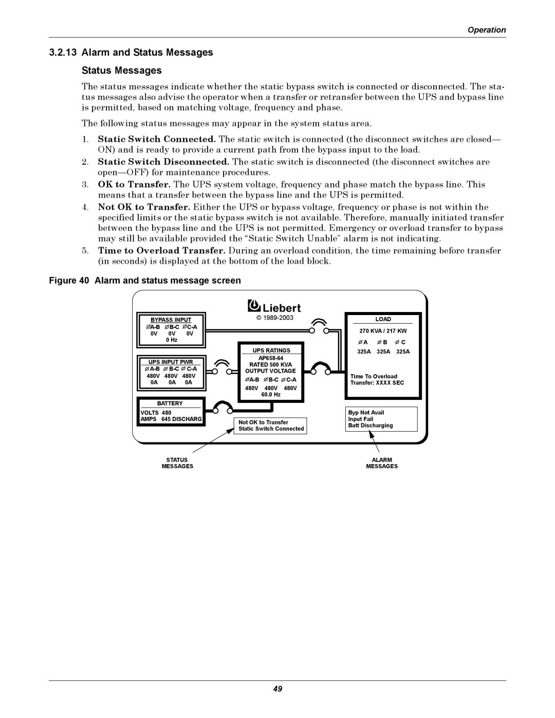
Figure 40 Alarm and status message screen
BYPASS INPUT
UPS INPUT PWR
BATTERY
VOLTS 480
AMPS 645 DISCHARG
©
UPS RATINGS
| ||
RATED 500 KVA | ||
OUTPUT VOLTAGE | ||
480V 480V 480V
60.0 Hz
Not OK to Transfer
Static Switch Connected
| LOAD |
|
270 KVA / 217 KW | ||
A | B | C |
325A | 325A | 325A |
Time To Overload | ||
Transfer: XXXX SEC | ||
Byp Not Avail
Input Fail
Batt Discharging
STATUS | ALARM |
MESSAGES | MESSAGES |
49