Operation
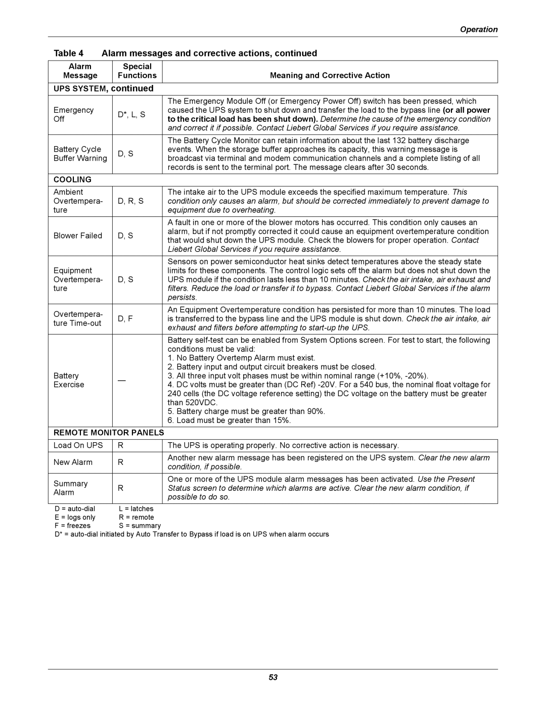
Table 4 Alarm messages and corrective actions, continued
Alarm
Message
Special
Functions
Meaning and Corrective Action
UPS SYSTEM, continued
|
| The Emergency Module Off (or Emergency Power Off) switch has been pressed, which | |
Emergency | D*, L, S | caused the UPS system to shut down and transfer the load to the bypass line (or all power | |
Off | to the critical load has been shut down). Determine the cause of the emergency condition | ||
| |||
|
| and correct it if possible. Contact Liebert Global Services if you require assistance. | |
|
|
| |
|
| The Battery Cycle Monitor can retain information about the last 132 battery discharge | |
Battery Cycle | D, S | events. When the storage buffer approaches its capacity, this warning message is | |
Buffer Warning | broadcast via terminal and modem communication channels and a complete listing of all | ||
| |||
|
| records is sent to the terminal port. The message clears after 30 seconds. | |
|
|
| |
COOLING |
|
| |
Ambient |
| The intake air to the UPS module exceeds the specified maximum temperature. This | |
Overtempera- | D, R, S | condition only causes an alarm, but should be corrected immediately to prevent damage to | |
ture |
| equipment due to overheating. | |
|
| A fault in one or more of the blower motors has occurred. This condition only causes an | |
Blower Failed | D, S | alarm, but if not promptly corrected it could cause an equipment overtemperature condition | |
that would shut down the UPS module. Check the blowers for proper operation. Contact | |||
|
| ||
|
| Liebert Global Services if you require assistance. | |
|
| Sensors on power semiconductor heat sinks detect temperatures above the steady state | |
Equipment |
| limits for these components. The control logic sets off the alarm but does not shut down the | |
Overtempera- | D, S | UPS module if the condition lasts less than 10 minutes. Check the air intake, air exhaust and | |
ture |
| filters. Reduce the load or transfer it to bypass. Contact Liebert Global Services if the alarm | |
|
| persists. | |
Overtempera- |
| An Equipment Overtemperature condition has persisted for more than 10 minutes. The load | |
D, F | is transferred to the bypass line and the UPS module is shut down. Check the air intake, air | ||
ture | |||
| exhaust and filters before attempting to | ||
|
| ||
|
|
| |
|
| Battery | |
|
| conditions must be valid: | |
|
| 1. No Battery Overtemp Alarm must exist. | |
|
| 2. Battery input and output circuit breakers must be closed. | |
Battery | — | 3. All three input volt phases must be within nominal range (+10%, | |
Exercise | 4. DC volts must be greater than (DC Ref) | ||
| |||
|
| 240 cells (the DC voltage reference setting) the DC voltage on the battery must be greater | |
|
| than 520VDC. | |
|
| 5. Battery charge must be greater than 90%. | |
|
| 6. Load must be greater than 15%. |
REMOTE MONITOR PANELS
Load On UPS | R | The UPS is operating properly. No corrective action is necessary. | |
|
|
| |
New Alarm | R | Another new alarm message has been registered on the UPS system. Clear the new alarm | |
condition, if possible. | |||
|
| ||
Summary | R | One or more of the UPS module alarm messages has been activated. Use the Present | |
Status screen to determine which alarms are active. Clear the new alarm condition, if | |||
Alarm | |||
| possible to do so. | ||
|
| ||
|
|
| |
D = | L = latches |
| |
E = logs only | R = remote |
| |
F = freezes | S = summary |
|
D* =
53