Operation
3.2.7Load Transfer Procedures Screen
Go to the Master Menu and move the highlighted cursor to LOAD TRANSFER PROCEDURES. Press the Select pad and the Load Transfer Procedures screen is displayed.
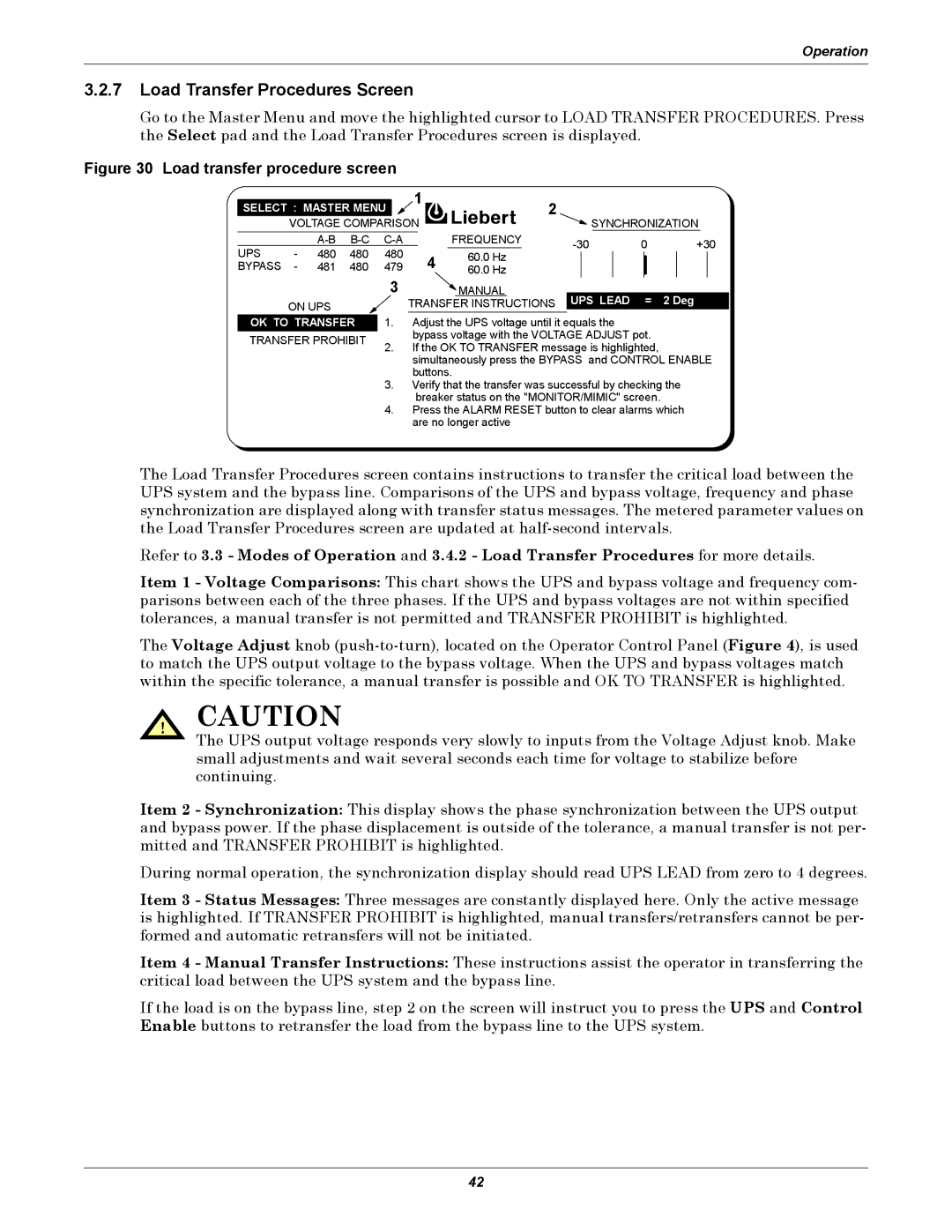
Figure 30 Load transfer procedure screen
|
|
|
|
|
|
| 1 | 2 |
|
|
|
|
|
|
|
| |||
| SELECT : MASTER MENU |
|
| SYNCHRONIZATION | |||||||||||||||
|
|
|
|
| |||||||||||||||
|
| VOLTAGE COMPARISON |
|
|
| ||||||||||||||
|
|
|
|
| FREQUENCY |
| 0 | +30 | |||||||||||
UPS | - | 480 | 480 | 480 |
|
|
|
|
| ||||||||||
4 | 60.0 Hz | ||||||||||||||||||
|
|
|
|
|
|
|
| ||||||||||||
BYPASS | - | 481 | 480 | 479 | 60.0 Hz |
|
|
|
|
|
|
|
| ||||||
|
|
|
|
| 3 |
|
| MANUAL |
|
|
|
|
|
|
|
| |||
|
| ON UPS |
|
|
| TRANSFER INSTRUCTIONS | UPS LEAD | = | 2 Deg | ||||||||||
|
|
|
|
|
|
|
|
|
|
|
|
| |||||||
|
|
|
|
|
|
|
|
|
|
|
|
|
|
|
|
|
|
| |
| OK TO TRANSFER | 1. | Adjust the UPS voltage until it equals the |
|
|
|
|
| |||||||||||
| TRANSFER PROHIBIT |
|
| bypass voltage with the VOLTAGE ADJUST pot. |
|
|
| ||||||||||||
| 2. | If the OK TO TRANSFER message is highlighted, |
|
|
| ||||||||||||||
|
|
|
|
|
|
|
| ||||||||||||
|
|
|
|
|
|
| simultaneously press the BYPASS and CONTROL ENABLE | ||||||||||||
|
|
|
|
|
|
| buttons. |
|
|
|
|
|
|
|
| ||||
|
|
|
|
| 3. | Verify that the transfer was successful by checking the | |||||||||||||
|
|
|
|
|
|
| breaker status on the "MONITOR/MIMIC" screen. |
|
|
| |||||||||
|
|
|
|
| 4. | Press the ALARM RESET button to clear alarms which | |||||||||||||
|
|
|
|
|
|
| are no longer active |
|
|
|
|
|
|
|
| ||||
The Load Transfer Procedures screen contains instructions to transfer the critical load between the UPS system and the bypass line. Comparisons of the UPS and bypass voltage, frequency and phase synchronization are displayed along with transfer status messages. The metered parameter values on the Load Transfer Procedures screen are updated at
Refer to 3.3 - Modes of Operation and 3.4.2 - Load Transfer Procedures for more details.
Item 1 - Voltage Comparisons: This chart shows the UPS and bypass voltage and frequency com- parisons between each of the three phases. If the UPS and bypass voltages are not within specified tolerances, a manual transfer is not permitted and TRANSFER PROHIBIT is highlighted.
The Voltage Adjust knob
! CAUTION
The UPS output voltage responds very slowly to inputs from the Voltage Adjust knob. Make small adjustments and wait several seconds each time for voltage to stabilize before continuing.
Item 2 - Synchronization: This display shows the phase synchronization between the UPS output and bypass power. If the phase displacement is outside of the tolerance, a manual transfer is not per- mitted and TRANSFER PROHIBIT is highlighted.
During normal operation, the synchronization display should read UPS LEAD from zero to 4 degrees.
Item 3 - Status Messages: Three messages are constantly displayed here. Only the active message is highlighted. If TRANSFER PROHIBIT is highlighted, manual transfers/retransfers cannot be per- formed and automatic retransfers will not be initiated.
Item 4 - Manual Transfer Instructions: These instructions assist the operator in transferring the critical load between the UPS system and the bypass line.
If the load is on the bypass line, step 2 on the screen will instruct you to press the UPS and Control Enable buttons to retransfer the load from the bypass line to the UPS system.
42