Operation
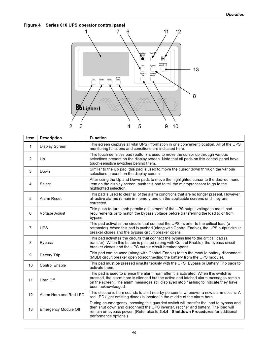
Figure 4 Series 610 UPS operator control panel
Item | Description | Function | |
1 | Display Screen | This screen displays all vital UPS information in one convenient location. All of the UPS | |
monitoring functions and conditions are indicated here. | |||
|
| ||
|
| This | |
2 | Up | selections present on the display screen. Note that all pads on this control panel have | |
|
| ||
3 | Down | Similar to the Up pad, this pad is used to move the cursor down through the various | |
selections present on the display screen. | |||
|
| ||
|
| After using the Up and Down pads to move the highlighted cursor to the desired menu | |
4 | Select | item on the display screen, push this pad to tell the microprocessor to go to the | |
|
| highlighted selection. | |
|
| This pad is used to clear all of the alarm conditions that are no longer present. However, | |
5 | Alarm Reset | all active alarms remain in memory and on the applicable screens until they are | |
|
| corrected. | |
|
| This | |
6 | Voltage Adjust | requirements or to match the bypass voltage before transferring the load to or from | |
|
| bypass. | |
|
| This pad activates the circuits that connect the UPS inverter to the critical load (a | |
7 | UPS | retransfer). When this pad is pushed (along with Control Enable), the UPS output circuit | |
|
| breaker closes and the bypass circuit breaker opens. | |
|
| This pad activates the circuits that connect the bypass line to the critical load (a | |
8 | Bypass | transfer). When this button is pushed (along with Control Enable), the bypass circuit | |
|
| breaker closes and the UPS output circuit breaker opens. | |
9 | Battery Trip | This pad can be used (along with Control Enable) to trip the module battery disconnect | |
(MBD) circuit breaker open (disconnecting the battery from the UPS module). | |||
|
| ||
10 | Control Enable | This pad must be pressed simultaneously with the UPS, Bypass or Battery Trip pads to | |
activate them. | |||
|
| ||
|
| This pad is used to silence the alarm horn after it is activated. When this switch is | |
11 | Horn Off | pressed, the alarm horn is silenced but the active and latched alarm messages remain | |
on the screen. The alarm messages still displayed stop flashing to indicate they have | |||
|
| ||
|
| been acknowledged. | |
|
|
| |
12 | Alarm Horn and Red LED | This electronic horn sounds to alert nearby personnel whenever a new alarm occurs. A | |
red LED (light emitting diode) is located in the middle of the alarm horn. | |||
|
| ||
|
| During an emergency, pressing this guarded switch will transfer the load to bypass and | |
13 | Emergency Module Off | then shut down and disconnect the UPS inverter, rectifier and battery. The load will | |
remain on bypass power. (Refer also to 3.4.4 - Shutdown Procedures for additional | |||
|
| ||
|
| performance options.) |
19