Operation
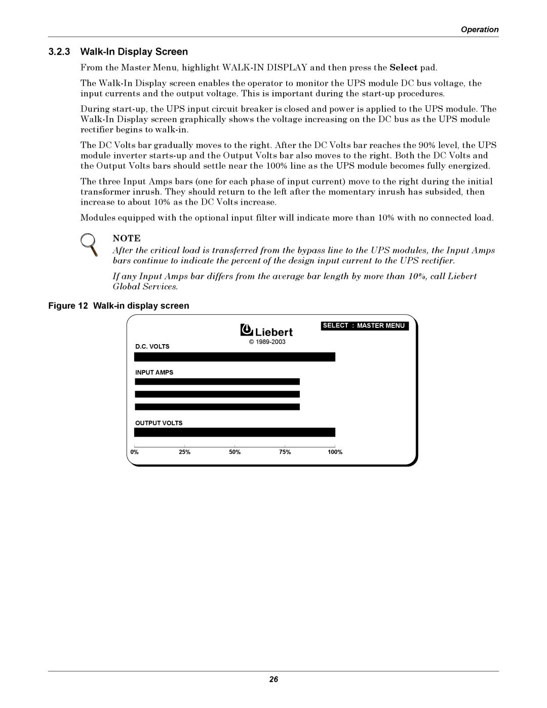
3.2.3Walk-In Display Screen
From the Master Menu, highlight
The
During
The DC Volts bar gradually moves to the right. After the DC Volts bar reaches the 90% level, the UPS module inverter
The three Input Amps bars (one for each phase of input current) move to the right during the initial transformer inrush. They should return to the left after the momentary inrush has subsided, then increase to about 10% as the DC Volts increase.
Modules equipped with the optional input filter will indicate more than 10% with no connected load.
NOTE
After the critical load is transferred from the bypass line to the UPS modules, the Input Amps bars continue to indicate the percent of the design input current to the UPS rectifier.
If any Input Amps bar differs from the average bar length by more than 10%, call Liebert Global Services.
Figure 12 Walk-in display screen
DOWN : | SELECT : MASTER MENU |
SELECT :
©
D.C. VOLTS
INPUT AMPS
OUTPUT VOLTS
0% | 25% | 50% | 75% | 100% |
26