Manuals
/
Lincoln Electric
/
Power Tools
/
Welder
Lincoln Electric
IM827-D
manual
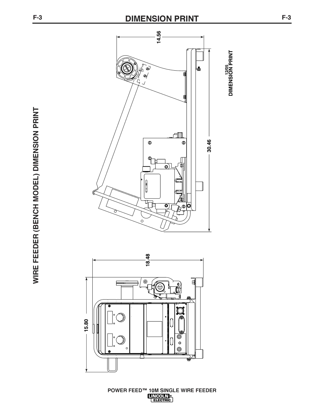
Dimension Print, 14.56 18.48 15.80, 30.46
Models:
IM827-D
1
72
75
75
Download
75 pages
15.54 Kb
68
69
70
71
72
73
74
75
Troubleshooting
Specification
Install
Error codes
Diagrams
Arc Start/Loss Error Time
Crater Delay
Power Feed 10M Wire Feeder
Dimension
Maintenance
Page 72
Image 72
F-3
DIMENSION PRINT
F-3
WIRE FEEDER (bENCH MODEL) DIMENSION PRINT
14.56
18.48
15.80
12/05
DIMENSION PRINT
30.46
POWER FEED™ 10M SINGLE WIRE FEEDER
Page 71
Page 73
Page 72
Image 72
Page 71
Page 73
Contents
Power Feed 10M Wire Feeder
Safety Depends on You
Safety
California Proposition 65 Warnings
Electric Shock can kill
Welding and Cutting Sparks can Cause fire or explosion
Iii
Précautions DE Sûreté
Please Examine Carton and Equipment For Damage Immediately
On-Line Product Registration
TAbLE of Contents
TAbLE of Contents
Installation
SPEC.# Type Input Power
Temperature Rating
Power Feed 10M Single Wire Feeder
Wire Drive Mounting See Figure A.1
Electric Shock can kill
Location
Mounting
Weld CAbLE SIzING
Weld CAbLE Connection
Weld CAbLE SIzES
Electrode Lead
COAxIAL Weld CAbLES
Negative Electrode Polarity
Control CAbLE Specifications
Control CAbLE Connections
AVAILAbLE Control CAbLE
Changing Drive Rolls and Wire Guides
Description
Drive Roll Pressure Setting
Changing the GUN Receiver bUSHING
Set the drive roll pressure by
To change the gun bushing
Welding GUNS, Torches and ACCES- Sories
GUN Receiver bUSHING
Magnum GUN and CAbLE ASSEMbLIES
Wire Feed Shut Down Circuit
Changing the Gear Ratio
To change the gear ratio
Wire Reel Loading
DIP Switch #8 Position Gear Ratio
Spindle Placement
Loading 16 to 44 lb .3 20kg Spools
Using K1504-1 Coil Reel
Figure A.10
Weld Wire Routing
Loading 30 lb .6 kg Readi-Reels See Figure A.11
Removing a Readi-Reel
13INSTALLATIONA-13
Shielding GAS Connection
ExAMPLES of Connecting AN Arclink Power Wave System
BOOM Configuration
Wire Drive
Control bOx
CV Welding Pulse Welding or STT Welding
Operation
Fumes and Gases can be dangerous
Welding Sparks can cause fire or explosion
ARC Rays can burn
Definitions of Welding Modes
Common Welding AbbREVIATIONS
Product Description
Recommended Processes
Required Equipment
Additional Required Equipment
Process Limitations
Equipment Limitations
Front Panel Controls and Connections
Status LED
Volts / Trim Display and Output KNOb
Prior to Welding
Synergic CV Voltage Display
Mode Select Panel 4 MSP4
Overview
LAYOUT-CONTROLS see Figure b.3
LAYOUT-DIGITAL Display
POWER-UP Sequence
Changing Weld Modes
Changing ARC Wave Control
Infrared IR Control
Limit Setting
Machine SETUP/USER Preferences
Accessing the Machine Setup Menu
SET-UP Features Menu
Figure b.3a Setup Menu
User Defined Parameters
Parameter Definition Procedure Change Method
Stall Factor Adjustment
Parameter Definition Gun Offset Adjustment
Crater Delay
Reset Consumable Weight
TIG Gas Control
Arc Start/Loss Error Time
Definition Push-Pull Gun Knob behavior
Display Trim as Volts Option
Sense From Studs
100 View Diagnostics
107 View Power Source Protocol
Parameter Definition Show Test Modes
101 View Event Logs
Cold Feed / GAS Purge Switch Step / 4-STEP Trigger Switch
Step Trigger
Step Trigger Operation
Step Trigger Operation
Sequence of Operation
Figure b.5
Process Setup and Operation
Non- Synergic
Modes
Steel and Stainless Synergic GMAW-P Pulsed MIG Welding
ARC Control
Pulse-on-Pulse Welding
Machine Functionality bY Weld Process
CC Stick Modes
Process Weld Mode
Output Control KNObS, Weld Mode 5
CV GMAW/FCAW NON-SYNERGIC
CV NON-SYNERGIC Modes
Wire SIzE 030 035 045 052
Gmaw Synergic
Synergic CV Modes
Material Process GAS
Wire SIzE
Pulse and PULSE-ON-PULSE Synergic
Pulse and PULSE-0N-PULSE Modes
STT and STT II Synergic
STT and STT II Modes
035 045 052
Gtaw TIG Welding
Gtaw Touch Start TIG Welding
Touch Start TIG
All Metals Touch Start TIG
DIP Switch Settings
User Memories
Limit Setting
High Limit
Low Limit
Attribute
Accessories
Optional
Accessories
Lb. coils to 2 spindles
Maintenance
Safety Precautions
Routine Maintenance
CALIbRATION Specification
1TROUbLESHOOTINGE-1
PRObLEMS POSSIbLE
Symptoms Cause Course of Action
Recommended
Err
No Heart beat response from See what to Do on Err
Error Codes for the Power Wave
TROUbLESHOOTING
Symptoms
Other
PRObLEMS
Cause Recommended Course of Action
Three Dashes
LINC-NET System Error Codes
Error Codes
Arclink System Error Codes
Field Service Facility
Your local Lincoln Authorized
PRObLEMS POSSIbLE
Output PRObLEMS
TROUbLESHOOTING
Recommended
Diagrams
Power Feed 10M Single Wire
Feeder
Diagrams
Dimension Print
14.56 18.48 15.80
30.46
Precaucion
Warnung
Top
Page
Image
Contents