OPERATION | ||
|
|
|
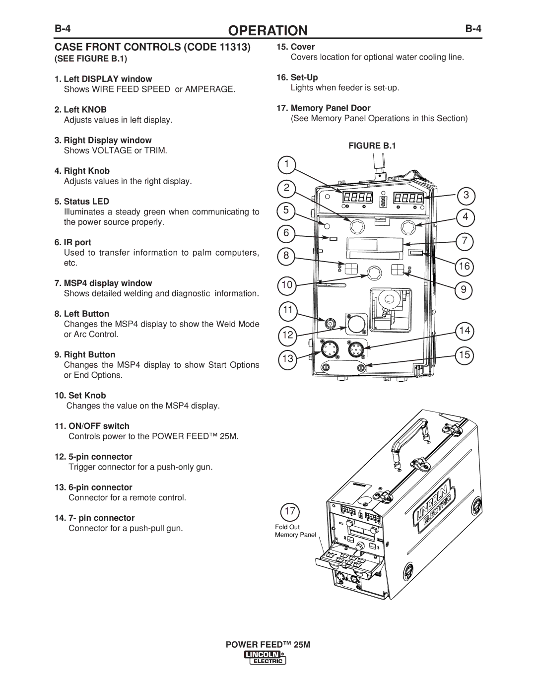
CASE FRONT CONTROLS (CODE 11313)
(SEE FIGURE B.1)
1.Left DISPLAY window
Shows WIRE FEED SPEED or AMPERAGE.
2.Left KNOB
Adjusts values in left display.
3.Right Display window Shows VOLTAGE or TRIM.
4.Right Knob
Adjusts values in the right display.
5.Status LED
Illuminates a steady green when communicating to the power source properly.
6.IR port
Used to transfer information to palm computers, etc.
7.MSP4 display window
Shows detailed welding and diagnostic information.
8.Left Button
Changes the MSP4 display to show the Weld Mode or Arc Control.
9.Right Button
Changes the MSP4 display to show Start Options or End Options.
10.Set Knob
Changes the value on the MSP4 display.
11.ON/OFF switch
Controls power to the POWER FEED™ 25M.
12.
Trigger connector for a
13.
Connector for a remote control.
14.7- pin connector
Connector for a
15.Cover
Covers location for optional water cooling line.
16.
Lights when feeder is
17.Memory Panel Door
(See Memory Panel Operations in this Section)
FIGURE B.1
1 |
|
2 | 3 |
| |
5 | 4 |
| |
6 | 7 |
| |
8 | 16 |
| |
10 | 9 |
|
11
12 ![]()
![]()
![]()
![]() 14
14
13 | 15 |
|
17
Fold Out
Memory Panel