OPERATION | ||
|
|
|
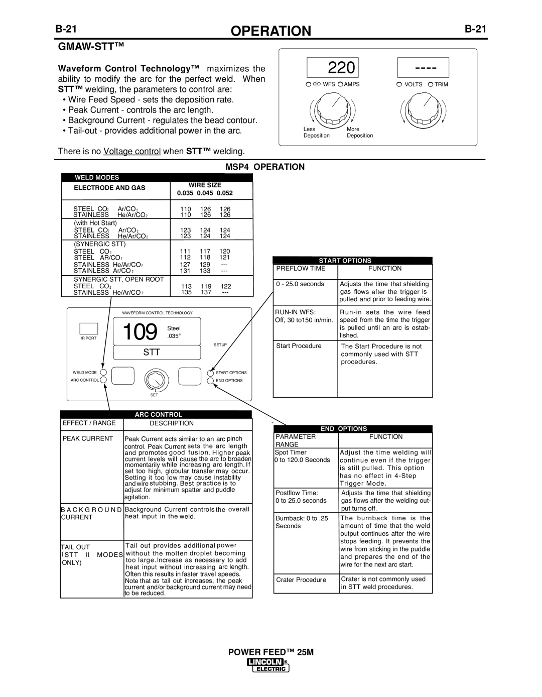
GMAW-STT™
Waveform Control Technology™ maximizes the ability to modify the arc for the perfect weld. When STT™ welding, the parameters to control are:
•Wire Feed Speed - sets the deposition rate.
•Peak Current - controls the arc length.
•Background Current - regulates the bead contour.
•
There is no Voltage control when STT™ welding.
220
![]()
![]()
![]() WFS
WFS ![]() AMPS
AMPS
LessMore
Deposition Deposition
VOLTS ![]() TRIM
TRIM
MSP4 OPERATION
WELD MODES
ELECTRODE AND GAS |
| WIRE SIZE | ||||||
| 0.035 | 0.045 | 0.052 | |||||
|
|
|
|
| ||||
STEEL CO2 |
| Ar/CO 2 |
| 110 | 126 |
| 126 | |
STAINLESS |
| He/Ar/CO2 |
| 110 | 126 |
| 126 | |
(with Hot Start) |
| 123 | 124 |
| 124 | |||
STEEL | CO2 |
| Ar/CO 2 |
|
| |||
STAINLESS |
| He/Ar/CO2 |
| 123 | 124 |
| 124 | |
(SYNERGIC STT) |
| 111 | 117 |
| 120 | |||
STEEL | CO | 2 |
|
|
| |||
STEEL | AR/CO2 |
| 112 | 118 |
| 121 | ||
STAINLESS He/Ar/CO2 |
| 127 | 129 |
| ||||
STAINLESS Ar/CO 2 |
| 131 | 133 |
| ||||
SYNERGIC STT, OPEN ROOT | 113 | 119 |
| 122 | ||||
STEEL | CO | 2 | He/Ar/CO 2 |
|
| |||
STAINLESS |
| 135 | 137 |
| ||||
|
|
| WAVEFORM CONTROL TECHNOLOGY |
|
|
| ||
|
|
| 109 | Steel |
|
|
| |
IR PORT |
|
| .035" |
|
|
| ||
|
|
|
|
| SETUP | |||
|
|
| STT |
|
|
|
| |
WELD MODE |
|
|
|
|
|
|
| START OPTIONS |
ARC CONTROL |
|
|
|
|
|
| END OPTIONS | |
|
|
|
| SET |
|
|
|
|
|
|
| ARC CONTROL |
|
|
| ||
EFFECT / RANGE | DESCRIPTION |
|
|
| ||||
PEAK CURRENT Peak Current acts similar to an arc pinch | ||||||||
|
|
| control. Peak Current sets the arc leng th | |||||
|
|
| and promotes go od fus ion. | Higher peak | ||||
|
|
| current | levels will cause the arc to broaden | ||||
|
|
| momentarily while increasing | arc length. If | ||||
|
|
| set too high, globular transfer may occur. | |||||
|
|
| Setting it too low may cause instability | |||||
|
|
| and wire stubbing. Best | practice is to | ||||
|
|
| adjust for minimum spatter and puddle | |||||
|
|
| agitation. |
|
|
|
| |
BA CKG | RO UND | Background Current controls the overall |
CURRENT | heat input in t he weld . | |
|
|
|
TAIL OUT |
| Tail out prov ides addi tio nal po wer |
( STT ll | MOD ES w ithou tt he molt en droplet beco min g | |
ONLY) |
| too large . Increase as necessary to add |
|
| heat input without increasing arc length. |
|
| Often this results in faster travel speeds. |
Note that as tail out increases, the peak current and/or background current may need to be reduced.
START OPTIONS | |
PREFLOW TIME | FUNCTION |
|
|
0 - 25.0 seconds | Adjusts the time that shielding |
| gas flows after the trigger is |
| pulled and prior to feeding wire. |
| |
Off, 30 to150 in/min. | speed from the time the trigger |
| is pulled until an arc is estab- |
| lished. |
Start Procedure | The Start Procedure is not |
| commonly used with STT |
| procedures. |
|
|
-
END OPTIONS |
|
| ||
PARAMETER |
| FUNCTION |
| |
RANGE |
|
|
|
|
Spot Timer | Adjust the time | weldin g w ill | ||
0 to 120.0 Seconds | conti nue even | if the tr | igg er | |
| is sti | ll pulled . This op | tion | |
| has | no e ffect i | n | |
| Trigg er Mode. |
|
| |
Postflow Time: | Adjusts the time that shielding | |||
0 to 25.0 seconds | gas flows after the welding out- | |||
| put turns off. |
|
| |
Burnback: 0 to .25 | The | burnba ck | time | is t he |
Seconds | amount of time that the weld | |||
| output continues after the wire | |||
| stops feeding. It prevents the | |||
| wire from sticking in the puddle | |||
| and prepares the end of the | |||
| wire for the next arc start. | |||
|
| |||
Crater Procedure | Crater is not commonly used | |||
| in STT weld procedures. | |||