THEORY OF OPERATION |
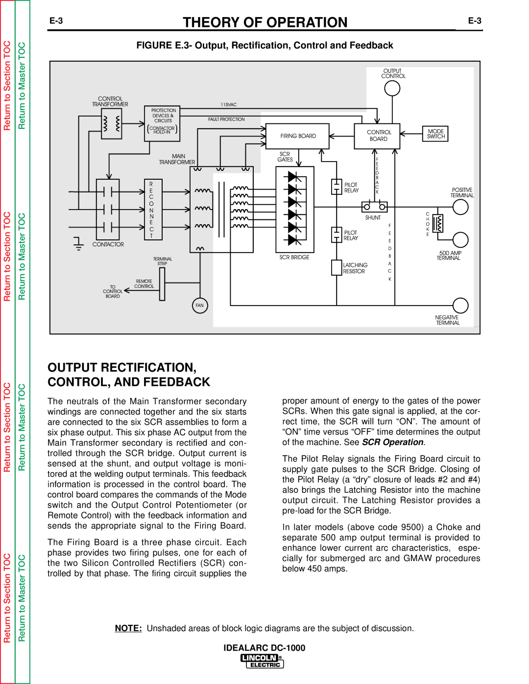
Return to Section TOC | Return to Master TOC | FIGURE E.3- Output, Rectification, Control and Feedback |
| ||
Return to Section TOC | Return to Master TOC |
|
|
| OUTPUT RECTIFICATION, |
| |
TOC | TOC | CONTROL, AND FEEDBACK |
| |
The neutrals of the Main Transformer secondary | proper amount of energy to the gates of the power | |||
Section | Master | |||
windings are connected together and the six starts | SCRs. When this gate signal is applied, at the cor- | |||
|
| |||
|
| are connected to the six SCR assemblies to form a | rect time, the SCR will turn “ON”. The amount of | |
to | to | six phase output. This six phase AC output from the | “ON” time versus “OFF” time determines the output | |
Main Transformer secondary is rectified and con- | of the machine. See SCR Operation. | |||
Return | Return | |||
trolled through the SCR bridge. Output current is | supply gate pulses to the SCR Bridge. Closing of | |||
|
| sensed at the shunt, and output voltage is moni- | The Pilot Relay signals the Firing Board circuit to | |
|
|
| ||
|
| tored at the welding output terminals. This feedback | the Pilot Relay (a “dry” closure of leads #2 and #4) | |
|
| information is processed in the control board. The | ||
|
| also brings the Latching Resistor into the machine | ||
|
| control board compares the commands of the Mode | ||
|
| output circuit. The Latching Resistor provides a | ||
|
| switch and the Output Control Potentiometer (or | ||
|
| |||
|
| Remote Control) with the feedback information and | ||
|
|
| ||
|
| sends the appropriate signal to the Firing Board. | In later models (above code 9500) a Choke and | |
|
| The Firing Board is a three phase circuit. Each | separate 500 amp output terminal is provided to | |
|
| enhance lower current arc characteristics, espe- | ||
TOC | TOC | phase provides two firing pulses, one for each of | ||
cially for submerged arc and GMAW procedures | ||||
the two Silicon Controlled Rectifiers (SCR) con- | ||||
below 450 amps. | ||||
trolled by that phase. The firing circuit supplies the | ||||
to Section | to Master |
| ||
|
| |||
Return | Return | NOTE: Unshaded areas of block logic diagrams are the subject of discussion. | ||
|
| |||
|
| IDEALARC | ||