Return to Section TOC
Return to Section TOC
Return to Master TOC
Return to Master TOC
TROUBLESHOOTING & REPAIR | ||
|
|
MAIN TRANSFORMER (T1) VOLTAGE TEST
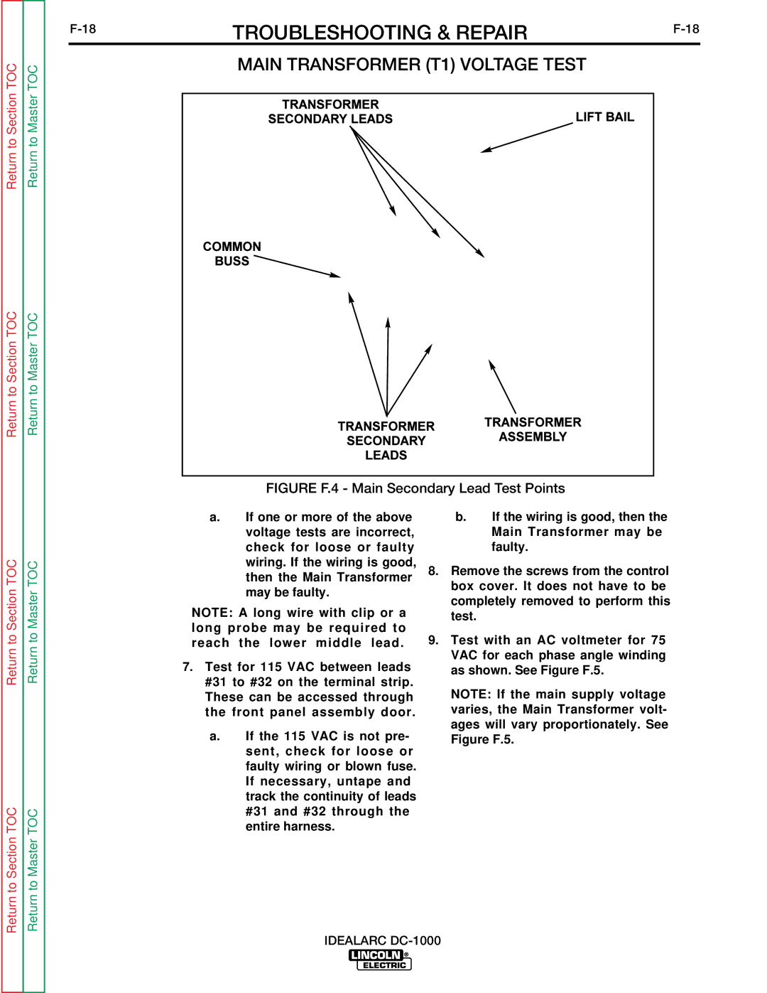
FIGURE F.4 - Main Secondary Lead Test Points
Return to Section TOC
Return to Section TOC
Return to Master TOC
Return to Master TOC
a.If one or more of the above voltage tests are incorrect, check for loose or faulty wiring. If the wiring is good, then the Main Transformer may be faulty.
NOTE: A long wire with clip or a long probe may be required to reach the lower middle lead.
7.Test for 115 VAC between leads #31 to #32 on the terminal strip. These can be accessed through the front panel assembly door.
a.If the 115 VAC is not pre- sent, check for loose or faulty wiring or blown fuse. If necessary, untape and track the continuity of leads #31 and #32 through the entire harness.
b.If the wiring is good, then the Main Transformer may be faulty.
8.Remove the screws from the control box cover. It does not have to be completely removed to perform this test.
9.Test with an AC voltmeter for 75 VAC for each phase angle winding as shown. See Figure F.5.
NOTE: If the main supply voltage varies, the Main Transformer volt- ages will vary proportionately. See Figure F.5.