Section TOC
Master TOC
TROUBLESHOOTING & REPAIR | ||
|
SCR OUTPUT BRIDGE REPLACEMENT
Return to
Return to Section TOC
Return to Section TOC
Return to
Return to Master TOC
Return to Master TOC
SCR OUTPUT BRIDGE
REMOVAL
1.Remove input power to machine.
2.Using a 5/16 (8mm) nut driver or flat head screw driver, remove 20 screws (ten per side) to remove case sides and 2 screws to remove top.
3.Using a 5/16 (8mm) nut driver or flat head screw driver, remove 6 screws, then lower the front control panel.
4.Remove the J4 gate lead Molex plug from firing board, and feed the plug down through the hole in bot- tom of the PC board compartment.
5.Using a 9/16” socket and
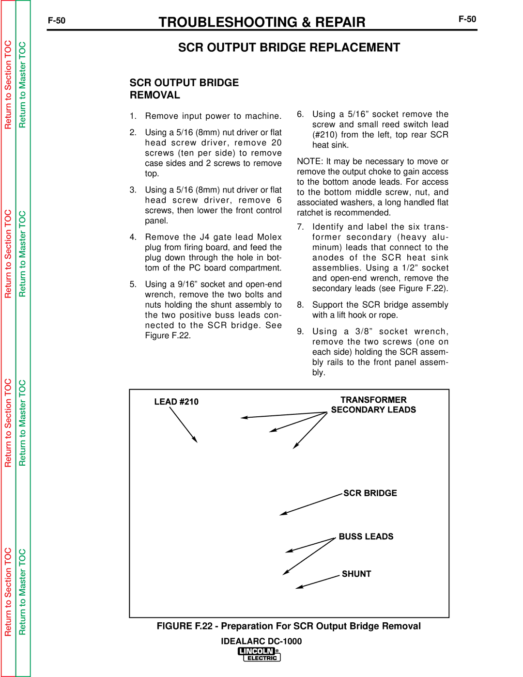
6.Using a 5/16” socket remove the screw and small reed switch lead (#210) from the left, top rear SCR heat sink.
NOTE: It may be necessary to move or remove the output choke to gain access to the bottom anode leads. For access to the bottom middle screw, nut, and associated washers, a long handled flat ratchet is recommended.
7.Identify and label the six trans- former secondary (heavy alu- minum) leads that connect to the anodes of the SCR heat sink assemblies. Using a 1/2” socket and
8.Support the SCR bridge assembly with a lift hook or rope.
9.Using a 3/8” socket wrench, remove the two screws (one on each side) holding the SCR assem- bly rails to the front panel assem- bly.
Return to Section TOC
Return to Master TOC