|
|
|
| INSTALLATION | |||||||||||||
|
|
|
|
|
|
| |||||||||||
TOC | TOC | OUTPUT CONNECTIONS | 3. Connect electrode lead to the desired terminal | ||||||||||||||
|
|
|
|
| (positive or negative) and tighten the output ter- | ||||||||||||
|
|
|
|
|
|
|
| ||||||||||
Section | Master | See Table A.1 for recommended IDEALARC | minal nut with a wrench. | ||||||||||||||
cable sizes for combined length of electrode and work | 4. Connect the second work lead to the other out- | ||||||||||||||||
|
|
| |||||||||||||||
|
|
| cables. |
|
|
| |||||||||||
|
|
|
|
|
| put terminal (positive if negative is attached and | |||||||||||
to | to |
|
|
|
|
| |||||||||||
|
| TABLE A.1 |
|
| vice versa) following steps 2 and 3. | ||||||||||||
Return | Return |
|
|
|
|
| |||||||||||
|
|
|
|
|
| AUXILIARY POWER | |||||||||||
| Suggested Copper Cable Sizes - 100% Duty Cycle |
| |||||||||||||||
|
|
| Combined Lengths of Electrodes and Work Cables |
|
|
|
|
|
|
|
|
|
| ||||
|
|
|
|
|
|
|
| This machine supplies the 115 volt, AC power need- | |||||||||
|
|
| Amperes |
| Length | Cable Size |
| ||||||||||
|
|
|
|
| ed for operating wire feeding equipment. The power | ||||||||||||
|
|
|
|
|
|
|
| ||||||||||
|
|
|
|
|
|
|
| ||||||||||
|
|
| 1000 |
| 0 - 250 ft. |
| is available from terminals #31 and #32 on the termi- | ||||||||||
|
|
|
|
| (76.2m) | (3 x 85.0 mm2) |
| nal strip. An 8 amp slow blow fuse on the machine | |||||||||
|
|
|
|
|
|
|
| control panel protects the auxiliary power from | |||||||||
|
|
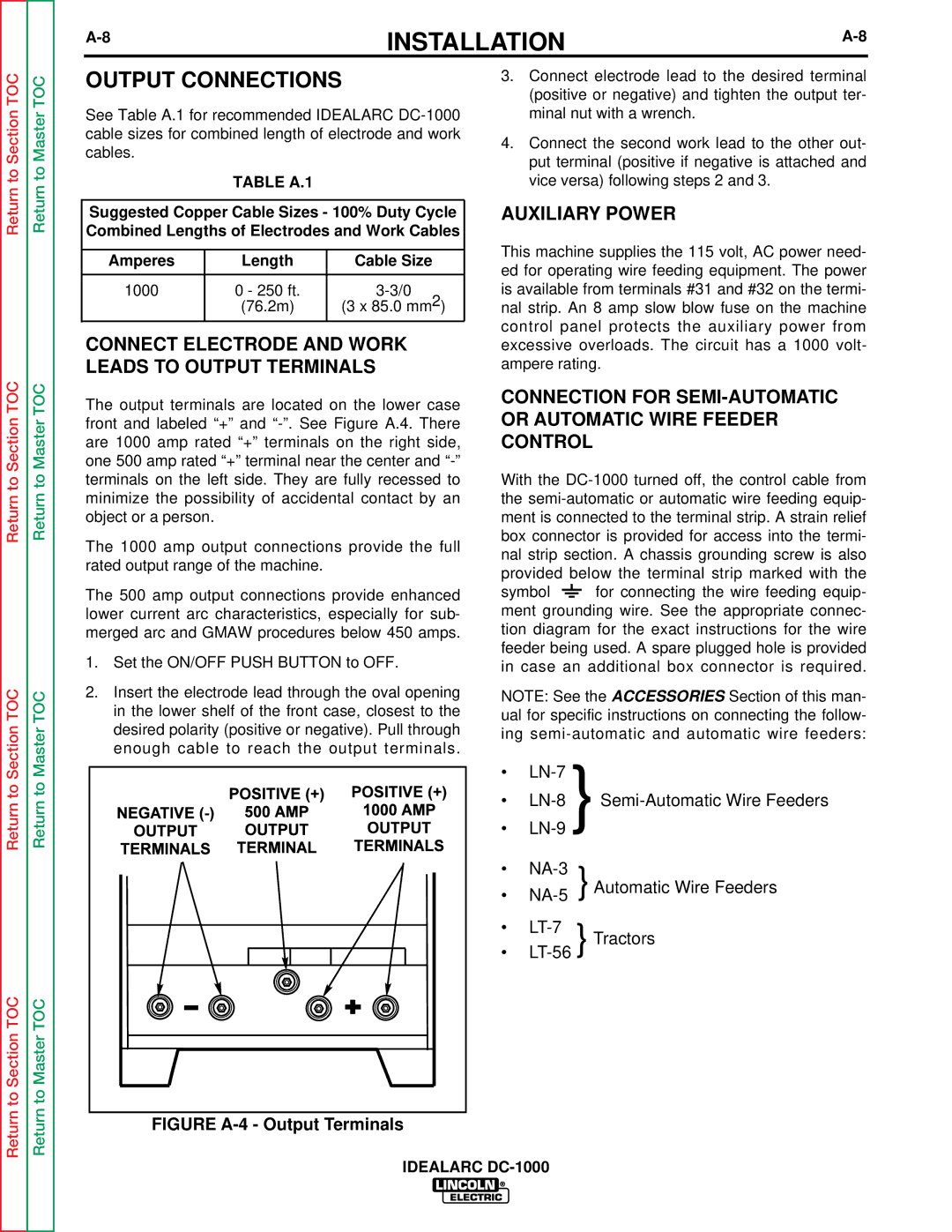
| CONNECT ELECTRODE AND WORK | ||||||||||||||
|
|
| excessive overloads. The circuit has a 1000 volt- | ||||||||||||||
TOC | TOC | LEADS TO OUTPUT TERMINALS | ampere rating. | ||||||||||||||
The output terminals are located on the lower case | CONNECTION FOR | ||||||||||||||||
|
|
| |||||||||||||||
|
|
| OR AUTOMATIC WIRE FEEDER | ||||||||||||||
Section | Master | front and labeled “+” and | |||||||||||||||
are 1000 amp rated “+” terminals on the right side, | CONTROL |
| |||||||||||||||
|
|
|
| ||||||||||||||
|
|
| one 500 amp rated “+” terminal near the center and |
|
|
|
|
|
|
|
|
| |||||
to | to | terminals on the left side. They are fully recessed to | With the | ||||||||||||||
minimize the possibility of accidental contact by an | the | ||||||||||||||||
Return | Return | ||||||||||||||||
object or a person. |
|
|
| box connector is provided for access into the termi- | |||||||||||||
|
|
|
|
|
| ment is connected to the terminal strip. A strain relief | |||||||||||
|
|
| The 1000 amp output connections provide the full | nal strip section. A chassis grounding screw is also | |||||||||||||
|
|
| rated output range of the machine. |
|
| ||||||||||||
|
|
|
|
| provided below the terminal strip marked with the | ||||||||||||
|
|
|
|
|
|
|
| ||||||||||
|
|
| The 500 amp output connections provide enhanced | symbol |
|
|
|
|
|
|
| for connecting the wire feeding equip- | |||||
|
|
|
|
|
|
|
|
|
| ||||||||
|
|
| lower current arc characteristics, especially for sub- | ment grounding wire. See the appropriate connec- | |||||||||||||
|
|
| merged arc and GMAW procedures below 450 amps. | tion diagram for the exact instructions for the wire | |||||||||||||
|
|
| 1. Set the ON/OFF PUSH BUTTON to OFF. | feeder being used. A spare plugged hole is provided | |||||||||||||
|
|
| in case an additional box connector is required. | ||||||||||||||
TOC | TOC | 2. Insert the electrode lead through the oval opening | NOTE: See the ACCESSORIES Section of this man- | |||
in the lower shelf of the front case, closest to the | ual for specific instructions on connecting the follow- | |||||
Section | Master | desired polarity (positive or negative). Pull through | ing | |||
enough cable to reach the output terminals. | • | } |
| |||
|
|
|
|
| ||
to | to |
| • | |||
Return | Return |
| ||||
| • |
| ||||
|
|
|
| |||
|
|
| • | } Automatic Wire Feeders | ||
|
|
| • | |||
|
|
| • | } Tractors | ||
|
|
| • | |||
to Section TOC | to Master TOC |
|
|
|
|
|
Return | Return | FIGURE |
|
|
|
|
|
|
|
|
|
| |
|
| IDEALARC |
|
| ||