Return to Section TOC
TOC
Return to Master TOC
TOC
TROUBLESHOOTING & REPAIR | ||
|
|
CONTROL BOARD TEST
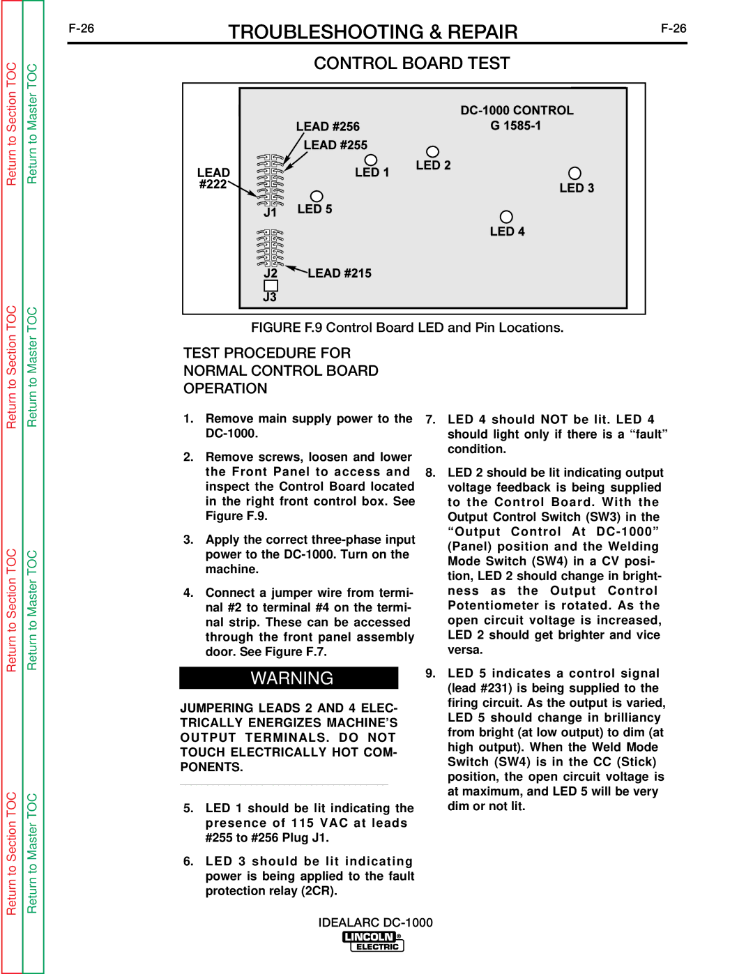
FIGURE F.9 Control Board LED and Pin Locations.
Return to Section
Return to Section TOC
Return to Section TOC
Return to Master
Return to Master TOC
Return to Master TOC
TEST PROCEDURE FOR NORMAL CONTROL BOARD OPERATION
1.Remove main supply power to the
2.Remove screws, loosen and lower the Front Panel to access and inspect the Control Board located in the right front control box. See Figure F.9.
3.Apply the correct
4.Connect a jumper wire from termi- nal #2 to terminal #4 on the termi- nal strip. These can be accessed through the front panel assembly door. See Figure F.7.
WARNING
JUMPERING LEADS 2 AND 4 ELEC- TRICALLY ENERGIZES MACHINE’S OUTPUT TERMINALS. DO NOT TOUCH ELECTRICALLY HOT COM- PONENTS.
______________________________________
5.LED 1 should be lit indicating the presence of 115 VAC at leads #255 to #256 Plug J1.
6.LED 3 should be lit indicating power is being applied to the fault protection relay (2CR).
7.LED 4 should NOT be lit. LED 4 should light only if there is a “fault” condition.
8.LED 2 should be lit indicating output voltage feedback is being supplied to the Control Board. With the Output Control Switch (SW3) in the “Output Control At
9.LED 5 indicates a control signal (lead #231) is being supplied to the firing circuit. As the output is varied, LED 5 should change in brilliancy from bright (at low output) to dim (at high output). When the Weld Mode Switch (SW4) is in the CC (Stick) position, the open circuit voltage is at maximum, and LED 5 will be very dim or not lit.