SP Switch Router Adapter Guide
Lucent Technologies
Contents
Chapter Configuring the SP Switch Router Adapter
Chapter
Appendix a Part Numbers
Appendix C
Viii SP Switch Router Adapter Guide 1.4 Update
Figures
Figures
Tables
Tables
About 1.4 Update
How to use this Guide
IBM SP system manuals
SP Switch Router manuals
Manual sets
Documentation conventions
Convention Meaning
IP routing publications
Introduction to the SP Switch Router Adapter card
What is the RS/6000 SP Switch Router ?
SP Switch Router
Cables included in your system
SP Switch Router systems for IBM sites
SP Switch cable
Redundant AC power supplies
Redundant supply safety
Pcmcia 520MB disk
Ethernet cable
Upgrading system memory
RAM
Overview of the SP Switch Router Adapter card
Face plate diagram
Inserting a media card into the SP Switch Router
Media card components
Card insertion procedure
ESD requirements
SP Switch Router Adapter card LEDs
LED activity during boot
OFF Error
OFF
TX HB
LED activity during normal operations
STATE1 Bottom two LEDs amber go on during
SP Switch Router Adapter card specifications
Element Value
Assigning filters
Tcpdump
Snmp on the SP Switch Router Adapter card
SP Switch Router Adapter dependent node MIB support
SP Switch Router Adapter media card states Snmp
Snmp configuration overview
Snmp activity during media card start up
Configuring the SP Switch Router Adapter
Introduction to installation and configuration
Pre-installation assumptions
Location of relevant information
Order of information
Installing an SP Switch Router Adapter card
Installation overview
Installing the Pcmcia spinning disk
Managing Pcmcia slots
Installation steps
Panic dumps sent to external flash device
file entries should now look like the following
Save all changes and reboot
Attaching SP Switch Router cables
SP switch cable
Do not damage the connector ends
Ethernet cable
Procedure for attaching cables to card and SP Switch
Keep the plastic cap on
Determining the switch connection for a dependent node
Configuration required on the SP system
Procedure
Sources of configuration information
Multiple frames for multiple system connections
SP system a
Overview of steps
Step-by-step media card configuration
Configuration files and their uses
SP Switch Router requires a specific configuration file
Check Snmp in the SP Switch Router system
Members
Unspecified Subagents
Put Snmp changes into effect
ALL GET SET Trap
Method 2 Optional, edit /etc/grifconfig.conf
Assign IP addresses
Method 1 Recommended, use SP Snmp Manager
Interface name
Internet address
Netmask
Broadcast / destination address
Default MTU values
Putting grifconfig.conf additions into effect
Argument field
MTU discovery facility
Specify Icmp throttling
Change profile settings
Specify card-level parameters Card profile
Specify different dump settings
Specify different executables
Configuring the SP Switch Router Adapter
Look at the SP Switch Router Adapter card settings
Change executables for all dev1 cards Load profile
Change dump defaults for all dev1 cards Dump profile
Dump vectors read-only
Configuring the SP Switch Router Adapter
Method 2 Optional, edit /etc/grdev1.conf
How to run the command
Run dev1config to create grdev1.conf
Contents of /etc/grdev1.conf
Parameter definitions
Extension Node Identifier ibmSPDepNodeName read-only
Configuration State ibmSPDepConfigState read-only
Reset card to install files
Saving configuration files
Verify SP Switch Router Adapter card from router
Verify media card operation using ping
Media card states
Verify switch node connectivity using ping
Check media card status using grcard
Reset media card using grreset
# grreset all -h # grreset slot -h
Checking connectivity to the SP system
Procedure
Configuring the SP Switch Router Adapter
Monitoring and Management Tools
flashcmd
SP Switch Router command overview
Csconfig
Getver
Grarp
Grcard
Grfins
Grreset
Grms
Grrmb
Grroute
Grstat
Grwrite
Mountf
Setver
Route
SP Switch Router Unix tools
Ping
Traceroute
Grroute.conf file
Using the netstat command
Netstat -rn
Netstat -rs
Netstat -in
Netstat -an
Netstat -s
Obtaining layer 2 and 3 statistics grstat
Options
Layer 3 statistics
List of IP stats
Multicast packets attempted to route
Layer 2 statistics
List of layer 2 stats
SP Switch Router Adapter card maint commands
Preparing to use maint commands
Sample maint commands
Find hardware and software version numbers maint
Find transmit tx binary version maint
Display configuration and status maint
Maint 5 display switch statistics
Maint 4 display media statistics
Filtering commands maint 50-58
Maint 6 display combus statistics
Configure UDP packet discards maint 89
List where filters are assigned maint
List the filters per media card maint
Display ARP table maint 189
Flush the ARP cache maint 189
Display switch route table maint 189
Switch route not found
Checking for hardware problems grdiag
What is tested
Where to find the user guide
Stopping or halting grdiag
When a media card does not boot after grdiag
Switch receive error can indicate hardware problem
SP Switch Router dumps
System dumps
Media card dumps
Use grdinfo to collect logs
Data collection utility grdinfo
Grdinfo -card=slot all
SP Switch Router example
Grdinfo -all
============================================================
Monitoring and Management Tools
Monitoring and Management Tools
SP Switch Router logs
Accessing a log file
Sample gr.console log
For example
Sample gr.boot log
Sample entries in the gr.boot log
Sample messages log
Sample entries in the messages log
Burning in media card flash memory
Part Numbers
Parts list model 04S
Parts list model 16S
GRF-AC-SWB16
GRF-AC-CB16
GRF-AC-AC16
Publication numbers IBM manuals
IBM publication number Manual title
Log Messages
Alphabetical list of messages
Log Messages
Access Fifo Sync Error from RC, int1=%d
Access Fifo Sync Error from TC, int1=%d
Message descriptions
ACK Words 0x%08x, 0x%08x, 0x%08x, 0x%08x, 0x%08x, 0x%08x
Board Configuration timed-out, retrying
ARP added IP= %s, SW-node=%d, state=%d
Bad Hdr/Svc received, Ret code=%d
CPU ready msg received from TX-CPU
Configuration Parameters
Configuring transmit side
Descriptor Sync Error from RC, int1=%d
Descriptor Sync Error from TC, int1=%d
Discarding msg, unknown msgtype 0x%x
ERR! Duplicated buffer %d
Expect Nodeinit but received Stat/Err Request
Expired IP buffer received %d
Hot interrupt detected, ier1=0x%8x, ier2=0x8x
Initializing Main Task
IOSTB3RX SET TOD service message received
Initializing RX Subsystem data structure
Loopback routes found for IP adr 0x%x, sw-node
Lost of STI clock, Tbic Status = 0x%x
NetStar GigaRouter %s RX Interface Initializing
NetStar GigaRouter %s TX Interface Initializing
RX Clock is valid
RX-CPU Loaded msg received from TX-CPU
RX send Sendtod to the switch. or RX Reading TBICs TOD
RX-TBIC outage errors detected IER1=0x%x, IER2=0x%x
RX-TBIC permanent errors detected IER1=0x%x, IER2=0x%x
RX got Tbic Inited fron TX
RX-TBIC transientt errors detected IER1=0x%x, IER2=0x%x
Send TOD service message received
Sending if Reset message to TX-CPU
Sending Grid Init Sending if Init for if 0x%x
State machine changes from xxx to yyy
Sending mib-2 trap, type = %d, state = %d
Sending params to TX
Status/Err service message received
Switch received with errors. Descriptor 0x%8x
Switch route entry not found, node = %d
Svc Msg rxed, svccmd=0x%x %s, nodecmd 0x%x %s
Switch Route table loaded, %d entries
TB4 segment received in error. TB4-HDR word%d 0x%x
TB4 segment received in wrong state
Tbic Init msg sent to TX-CPU
Tbus Parity Error from RC, int1=%d
Tbus Parity Error from TC, int1=%d
TBSI-RX TBICs TOD 0x%x, 0x%x
TBSI-TX Unexpected SVC threshold interrupt
Timeout waiting for Cfgdn bits clear, stat0=%x
Timeout waiting for FPGAINITCOMPLETE, stat0=%x
RX Setting the RC in operational mode, stat=0x%x
TX-CPU Access Fifo busy, discarding IP packet
Timed out resolving ARP. If %d IP %d.%d.%d.%d
TX-CPU Config Params msg received from RX-CPU
TX-CPU Tbic Init msg received from RX-CPU
TX Port is connected, stat=0x%x
TX-PROR startnode %d, endnode %d, # entries %d
TX pseudo STI clock is valid
TX-TBIC outage errors detected IER1=0x%x, IER2=0x%x
TX-TBIC permanent errors detected IER1=0x%x, IER2=0x%x
TX-TBIC transient errors detected IER1=0x%x, IER2=0x%x
Un-expected descriptor from RC, desctype=%d
Log Messages
Network Configuration Examples
Configuration requirements
Example 2 Multiple cards, single partition
ARP table
Outgoing traffic coming from SP processor nodes
Configuration tasks
Incoming traffic going to SP processor nodes
Recovery procedure if an SP Switch Router Adapter card fails
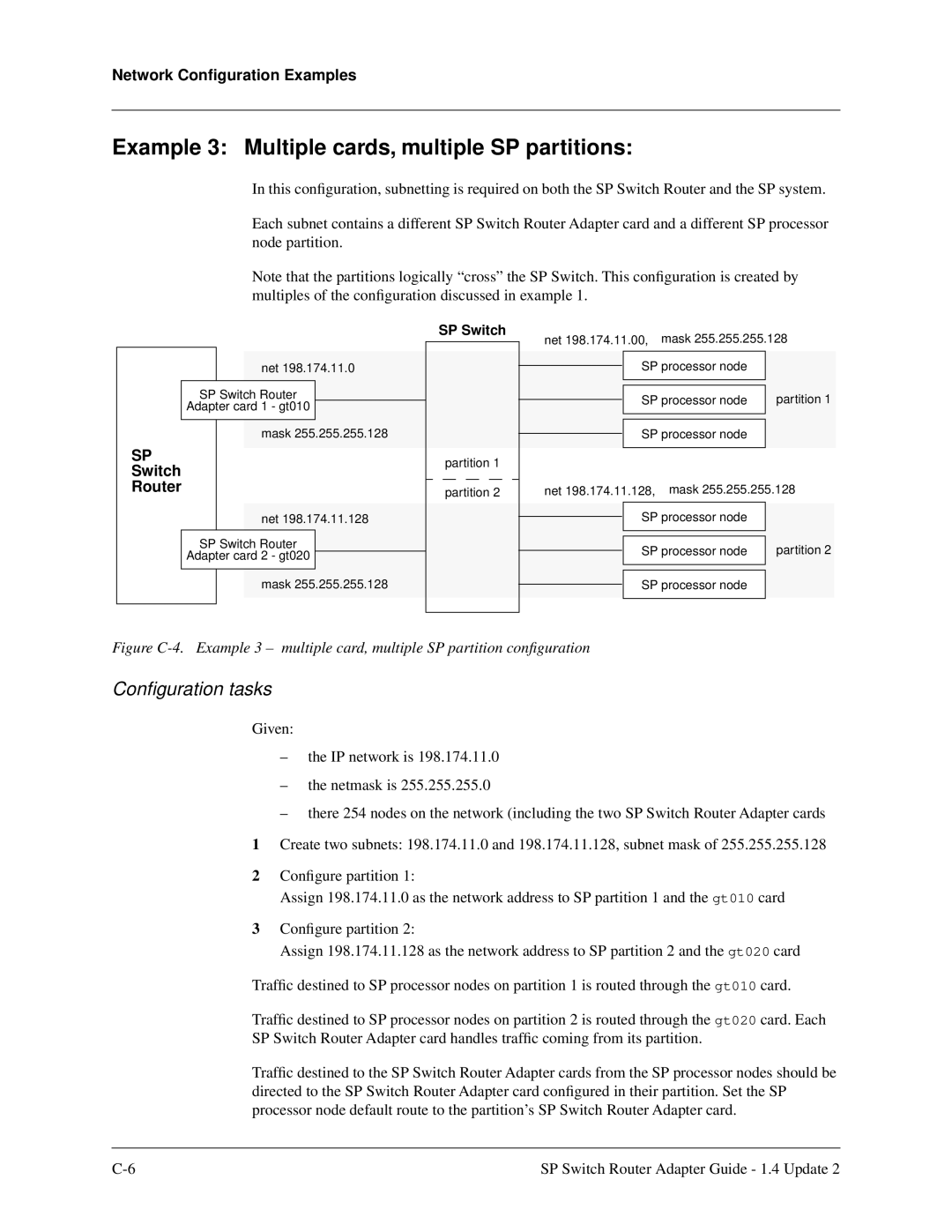
Example 3 Multiple cards, multiple SP partitions
Obtaining new machine code
SP Switch Router as an IBM product
Support for code installation
IBM License Agreement for Machine Code
Index
ARP
Index
GRF
IBM
Index
MTU
Snmp
Index
Index