Motorola
Restricted Rights Notification for U.S. Government Users
Proprietary Material
Page
Contents
Installing the Modem
Using the AT Automatic Calling Interface
Appendix B. Cabling and Interface Pinouts
Glossary Return Procedures
Contents
Product Family Model Numbers
Using the Documentation Set Overview
326X Series Modem Family
This Model Number... Denotes
Documentation Target Audience
Using the Documentation Set
How to Use the Documentation Set
326X V.34 Series Modem Reference Card T0009-01
326X V.34 Series Modem User’s Guide T0009
326X Series Modem Reference Guide
References
Trademarks
Using the Documentation Set Conventions
Special Notices
Avertissement
Messages spéciaux
Mise en Garde
Besondere Hinweise
Advertencia
Using the Documentation Set Avisos Especiales
Precaucion
Xviii
Motorola Information System Group ISG Customer Information
Introduction
Questions about Billing
Sales-Related Issues Information on Product Training
Motorola ISG Customer Information
Comments about the Manual
User Documentation
Xxii
Customer Response Card
Business Reply Mail
Contents
Chapter
Introduction
From a network management system NMS
Safety and Operational Notices
Repair
Operating the Modem from the Front Panel
Lightning
25bis ACU
Selecting Programmed Option Sets
Automatic Calling Interfaces ACUs
Managing a Modem
ITU-T V.34 Compliant Modulation Mode
Modulation Mode Characteristics
Restoring Data Transmission
Compatibility in V.34 Modulation Mode
Synchronous Data Compression SDC Feature
Automode/Multimode Feature
Security
Remote Configuration
Error Correction and Data Compression
Status Snapshots
Country-Specific Information
Troubleshooting V.54 and V.22bis Tests
Adaptive Rate System
NET Compliance
Modem
Installing the Modem
Chapter
Appendix C Appendix B
One User’s Guide One Reference Card
Unpacking the Modem
U.S.A Outside the U.S.A
Additional Equipment Required
Choosing a Site
An AC power switch
Connecting the Modem
Rear Panel Connectors
Modular jacks for making
Electrical Interfaces-EIA/TIA-232 and ITU-TS
Operating at V.34 DTE Rates
Models 3267
Ferrite Cylinders
Models 3261 and 3266 Dial Line Connections
Modems
Installing a Ferrite Cylinder on an Audio Cable
Installing a Ferrite Cylinder on a DTE Cable
Installing a Ferrite Cylinder on a Power Cable
Installing a Ferrite Cylinder on a Power Cable
Important Information About the Modulus Enclosure Front Door
Important Information About the Modulus Enclosure
Cabling the Modem
3265 Modem Cabling
Connecting the Modem to a Network Management System
Connecting to a 9110 NMS
11. Connecting Modems in a Daisy Chain Configuration
Turning on the Modem
Automatic Self-Test
After Installing the Modem
Handling Error Messages
Self-Test Messages
Installing the Modem
Contents
Getting Started
Using the Front Panel
System Requirements for Software Upgrades
Configuring and Operating the Modem
If You Are Unsure of Your DTE’s Data Format
Name Description
326x Ready
326X LEDs
Front Panel Display
RC/NC
Menu Structure
Navigating the Configuration Menu Tree
Setting Configuration Options from the Front Panel
Front Panel Keys
Status Displays
Example Accessing a Configuration Option
Talk/Data Switch
Operating Status Displays
Using the Modem with a Network Management System NMS
Where Do I Go from Here?
Option Sets/Dialing Options
Using the AT Automatic Calling Unit ACU
Using the Modem with an Async Terminal
Using the Modem with a PC and Async Communications Software
Selection, refer to
NetView LPDA-2 ACU for Sync Applications
Other Call Establishment Methods
25bis ACU for Sync or Async Applications
NetView LPDA-2 ACU for synchronous applications
Sync Dialing from an IBM AS
External Auto-Call Units
Page
Configuring the Modem
Option Set 4-Synchronous Leased Line Applications with
Communications Software Package Operating Notes
Configuring the Modem for Use with Communications Software
Select the Modem’s Preconfigured Option Set
Operating Notes
General Notes
Direct Operating Mode
Set Modem Flow=Off
If the Communications Software and Modem Do Not Operate
Reinitializing Memory Using the AT&F Command
Preparing for Operation
Reinitializing Memory from the Front Panel
Option Set Summary-326X V.32bis and V.34 Modems
Configuration Option Sets
What is an Option Set?
Option Set Summary-326X FAST-SDC Modem
Option Set 1-Async Calls to Central Site Using the AT ACU
Option Set Descriptions-326X V.32bis and V.34 Modems
Option Set Descriptions-326X FAST-SDC Modems
Option Set 2-Sync Dial A/B Restoral
Option Set 3-Sync Dial Only
Configuring an Option Set
To create a customized option set
Do not turn off modem power until Save COMPLETED! appears
Save Changes=n
Option Set Defaults
Option Set Defaults-326X V.32bis and 326X V.34 Modems
Option Set Parameter 3260/62/65/67 3261/63/66/68
Terminal OPT’S
XON/XOFF
Option Option Set 3261/63/66/68
Option Set Defaults-326X-SDC V.34 Modem
Option Set
DTE Rate Auto 56.0 U.S. A., Canada Other countries Flow
Ext Cntrl Pin Inactivity S30
326X V.32bis and 326XFAST Modem Application Examples
For This Type of Application Select
Option Set 1-Async Calls to Central Site Using AT ACU
Changing Default Configuration Settings
Option Set 2-Sync Answering Central Site Without ACU
Option Set 3-Sync Calls to Central Site, V.25bis ACU
Synchronous Dialing from an IBM AS
326XFAST-SDC Modem Application Examples
Mode=Originate in the other modem
Operational Requirements
Configuring the Modem for SDC Operation
SDC Pre-Operation Notes
Optimizing Network Performance
SDC Sample Applications
Ensuring Optimum Network Performance in SDC Mode
SDC Option Set 1-Async Calls to Central Site Using AT ACU
SDC Option Set 2-Sync Dial A/B Restoral
To 33.6 kbps
SDC Option Set 3-Sync Dial Only
X-SDC Dial-Only Application-Option Set
Bandwidth On Demand
Bandwidth On Demand-Option Set
Point-to-Point Leased Line Application with Dial Restoral
Select SDC Option Set 4 for this application
Operation
Remote Access Reset
When Remote Access Reset Is Disabled
Configuring the Modem
Using the AT Automatic Calling Interface
Industry-Standard AT Command Set-AT and AT
Entering AT Command Lines
What is the Attention AT Command Set?
Using AT Commands
To enter a single AT command line
For Further Detail on AT Commands
To enter multiple AT commands on a single command line
AT Command String Examples
Interpreting AT Command Strings
Valid Autobauding Character Formats
Autobaud Feature
Escape Sequence-+++
Start Bit Data Bits Parity Stop Bits
Non-Configuration AT Commands
To use the escape sequence with guard time
ATD, Dial
Re-Execute Last Command
ATA, Manual Answer
ATI, Display Software Information
ATO, Leave Command Mode
ATH, Hang Up
Displaying and Changing S-Register Values
Registers
AT*RD, Redial Last Number
Display S-Register Value ATSn?
Change S-Register Value ATSx=n
Register Descriptions
Display S-Register Value AT?
Change S-Register Value AT=x
Register 3-Carriage Return Character
Register 1-Ring Count
Register 2-Escape Code Character
Register 4-Line Feed Character
Register 7-Wait for Data Carrier
Register 5-Backspace Character
Register 6-Wait for Dial Tone
Register 8-Pause Time for Pause Delay Dial Modifiers
Register 10-Carrier Loss Hang Up Delay
Register 12-Escape Code Guard Time
Register 18-Test Timer
Register 11-DTMF Tone Duration
Register 30-DTE Inactivity Disconnect
Register 25-Delay Before Looking for DTR
Register 26-RTS/CTS Delay
Register 46-Access Security Lead Digit Delay Timeout
Register 38-Disconnect Buffer Delay
Register 45-Access Security Tone Duration
Register 96-Signalling System #5
Register 97-Break Signal Duration
Register 98-AC Detect
Register 99-V.32 Training Time
Troubleshooting Guide
Assumptions
Troubleshooting
Troubleshooting Steps
First Step
Call Establishment
Max Rate AT*MX Min Rate AT*MN
Data Mode
Flow control
Call Termina Tion
Fast Call=Off AT*FC0 in it
Modem won’t connect
326X Series Modem Diagnostic Tests
Test Description Command
Synchronous Data Compression SDC Testing
To initiate a test from the modem’s front panel
Page
Configuration Quick Reference
Appendix a
For More Detail
Configuration Quick-Reference-Menu Trees
Configuration options and functions
Audience and Assumptions
Figure A-1. The 326X Series Modem Menu Structure Part 1
Figure A-2. The 326X Series Modem Menu Structure Part 2
Figure A-3. The 326X Series Modem Menu Structure Part 3
Figure A-4. The 326X Series Modem Menu Structure Part 4
Async Echo
Dial From
Stored #=n
Dial
Volume
Speaker
RsltCode
Longspace
Select Options
Guard Tone
Reinitialize Memory
Guard Tone
Display Modem ID
AT Form
Telco
Line
Pulse Cycle
Mode=Direct
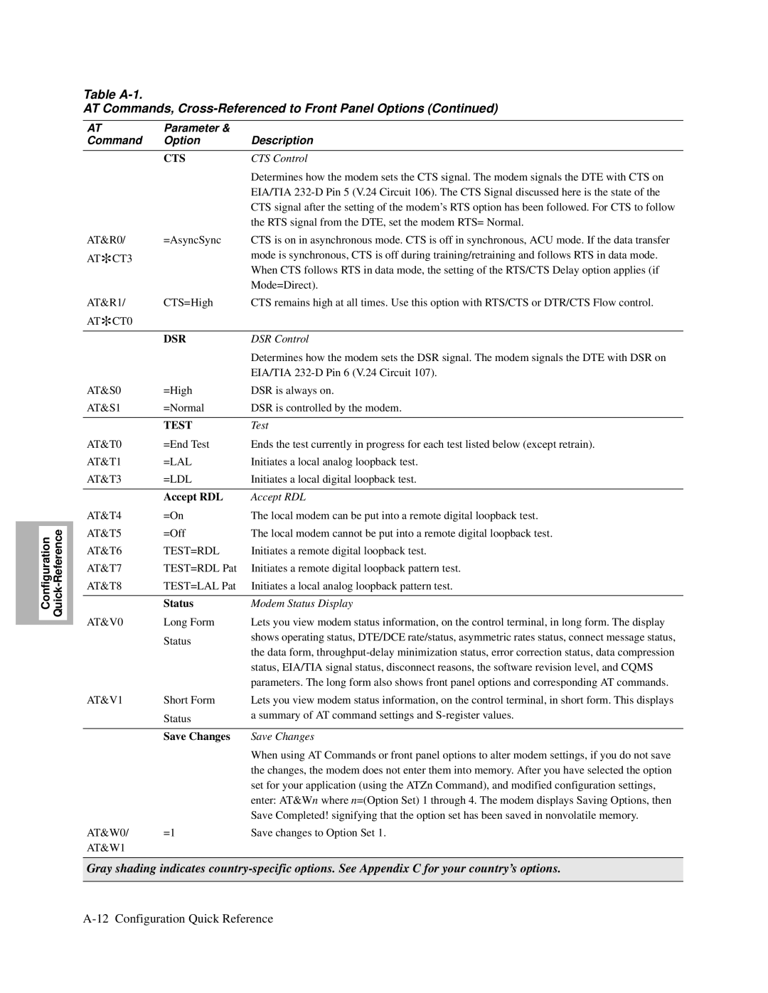
RTS signal from the DTE, set the modem RTS= Normal
CTS Control
DSR Control
Enter Phone #
Power Up
Clock
Answer
Asym Rate
Ans Rest
Break
Auto Type
Blind Dial
Mode
Buffer Delay
See the AT&Z command description
Default Dialing
=Off Off setting disables the Delay option
Dial Wait
Data Compression
Dial Wait
DTE Rate
To D
RTS/CTS Delay
Data Form
Auto Redial
Pause Delay
DTR Delay
Stored#
Flow
Flow Control
Line Compen
Hold DL Line
DTE Ct
To L
Link Phone #’s
Pstn Signaling
LAL Busy Out
Low Speed
Min Rate
Modem Flow
Mod
Max Rate
AT Msg
AT Message
Maximum Rate
View Phone #
Buffers
Netwrk Comp
Ext Cntrl
Set Protection
Password
Overspeed
Unlock Pass
Word
Restore
Change Pass
Rmt Acc
RTS Control
Parity
Parity
Retrain
Speed Conver
Inactivity
RemRTS/DCD
RTS/DCD Remote Signaling
Throughput Minimization Delay
TpDlyMin
Tone Length
Call Timeout
Call Timeout
Tone Length
Displays only when selected by an NMS
Callback Feature
Access security password from the remote modem
This command defines dial command limitations
Sim Ring
Password Verification
Rem Num Rqrd Remote Number Required
Simulated Ringback
Table A-2 Front Panel Configuration Options
LPDA2 Addr
Sync Idle
V25 Resp
LPDA2 Det
NC Address
Group PW
OverrideMode
NC PortRate
Performing Numeric Entry
Front Panel Option Description
Table A-3 Register Cross-Reference
Register/AT Command Cross-Reference
Register AT Command Front Panel Option
Modifier Function Description
Dial Modifiers for Special Dialing Requirements
Table A-4 Dial Modifiers
Table A-4 Dial Modifiers
Result Codes
Table A-5 Result Codes
Connect
Configuration Quick Reference A-43
Switch Number Setting Function
Configuring the Modem’s Dual In-line Package DIP Switches
Table A-6 Rear Panel Switches
Configuration Quick Reference A-45
Page
Appendix B
Cabling and Interface Pinouts
EIA/TIA 232-D Modem to Computer Interface
326X/326X-SDC cabling requirements and diagnostics
Pin 232-D ITU Signal Definition
Table B-1 Modem/Computer Interface Connections
Models 3261/3263/3266/3268 only. Signal passed from modem to
ITU Recommendation V.35 Modem-to-Computer Interface
Figure B-1 XFAST-SDC Series Modem with ITU V.35 Interface
Table B-2 ITU V.35 Modem/Computer Interface Connections
Pin Signal Definition
ITU Rate V.35 Modem-to-Computer Interface Pinouts
Dial LINE, Lease Private LINE, Phone Connector Pinouts
Differences, EIA/TIA 232-D and ITU Rate V.35 Interfaces
Cabling
Table B-3 Network Control Port Connector Pinouts
NC Network Control Port Pinouts
Cable Considerations
Table B-4 Maximum Cable Capacitance per Data Rate
Table B-5 Motorola DB-25 Low Capacitance Cables for
Motorola Product Up to Description Code Kbps ft Kpbs ft
DTE Cable Diagnostics
Table B-6 Vendor Wire for
Cabling and Interface Pinouts B-11
Page
Appendix C
Canada
Country Support
Models 3265/3266
Installation Notes
Restricted Features Summary
All Models
Setting AT Command
AT*AA1
Feature Australia Austria Belgium Canada
Czech Republic Feature Poland Denmark Finland France
Feature Germany Hong Kong Ireland Israel
Feature Italy Japan Malaysia Netherlands
AT*DR1 AT*DR2 AT*DR3 AT*DR4 AT*LL
Feature Norway Portugal South Africa Spain
AT*DD2 AT*DD3
AT*DD3 S7 AT*DD9 AT*DP
Feature Sweden Switzerland United Kingdom Universal
AT*DD4 AT*DD3
AT*DR1 AT*DR2 AT*DR3 AT*LL
Operating Notes
Standalone Modem Rear Panel Views
Modem Rear Panel Dial Only
Dial Only Modem
Modem Rear View Leased Line, Dial Restoral
Modem Rear Panel-View a
Figure C-3.View a Rear Panel Layout 3265 Dial Only
Modem Rear Panel-View D
Modem Rear Panel-View B
Modem Rear Panel-View C
Modem Leased Line with Dial Restoral
For an Illustration of the Enclosure Card Backplane
Standalone Models 3260/65 and 3261/66 Interface Pinouts
Wire Leased Line Interface Models 3260/3265
Rear Panel Interface Pinouts
Dial Line Interface Models 3260/3265
Dial Line Interface Models 3261/3266
Phone Connector Interface Models 3260/3265
Wire Leased Line Interface Models 3261/3266
Table C-6 Wire Leased Line Interface Models 3261/3266
Dial Line Interface All Card Models
Phone Connector Interface Models 3261/3266
Card Models 3262/67, 3263/68 Backplane Interface Pinouts
Table C-7 Phone Line Interface Models 3261/326
Table C-9 Wire Leased Line Interface Models 3262/3267
Wire Leased Line Interface Models 3262/3267
Wire Leased Line Interface Models 3263/3268
Table C-10 Wire Leased Line Interface Models 3263/3268
Austria-Forbidden Call Lists
Delayed and Forbidden Lists
Australia-Delayed Call Lists
Belgium-Delayed Call Lists
Finland-Delayed Call Lists
France-Delayed and Forbidden Call Lists
Hong Kong-Delayed Call Lists
Ireland-Delayed Call Lists
Netherlands-Delayed Call Lists
Norway-Delayed Call Lists
Canada
Spain-Delayed Call Lists
Other Country-Specific Information
DOC Registration and Requirements
Industry Canada Equipment Attachment Limitations
Canadian Emissions Statement
Rear Panel Pinouts
Table C-12 Dial Line Connector Pinouts for Jack Operation
Table C-13 Phone Connector Pinouts for Jack Operation
Modem
Telco Option AT&J
Table C-14 Dial Line Connector Pinouts for Jack Operation
Table C-15 Phone Connector Pinouts for Jack Operation
Compliance with BS6328 Part 1 1982 Section
Denmark-Blind Dialing
Hong Kong and United Kingdom-BABT Regulations
Ringer Equivalence Number REN
Compliance with BABTSITS/82/01/C and BABT/SITS/ 82005S/D
Compliance with BS6305 Clause 6.2, BS6320 Clause
Compliance with BABT/SITS/83/08/A Clause
Compliance with BS6789 .11986 Clause
Compliance with Babt Sits 83/009 Section D
Compliance with DTI 83/009I
Compliance with BS6301
FCC Registration
Installation of Telephone Socket
Application for Installation of Telephone Socket
FCC Regulations
Pin Data Jack Programmable
Dial Line Jack Types
Pin Voice Jack Permissive
Jack Type Description
Jack Leased Connector Pin No Function
Table C-16 Dialline Connector Pinouts for Jack Operation
Table C-17 Phone Connector Pinouts for Jack Operation
Dial Line Telco Jack Selection
Table C-18 Dial Line Connector Pinouts for Jack Operation
Table C-19 Phone Connector Pinouts for Jack Operation
Making Telephone-to-Modem Connections
Connecting an Exclusion Key Telephone
Dial and Leased Line Transmit Levels
Dial Line Transmit Level
Declaring The Jack Type
RJ4MB4
Using the Modulus Backplane’s Busy Out Feature
Pin Pair Function A. and Canada Other UI Countries
Table C-20. Backplane Pin Settings for Busy Out, Modulus
Table C-21. Backplane Pin Settings for Busy Out, Modulus
Modem a Modem B
Country-Specific Information
Glossary
ACU
CRC
EIA
ITU-TS
Pstn
SYN
Return Procedures
Factory Repair
Equipment Return Procedures
Expiration of Lease
Packaging Guidelines for Equipment Return
Index
DOC
FCC
Phone
SDC
Index-6