10 | Chapter 1 System Description |
Table 1-5 Configuration of MFU
No. | Component | Description |
1 | SPD | Norminal Dischage Current(8/20μS) 20kA; Ue=385V |
|
|
|
2 | AC input terminals | Rating Current 150A |
|
|
|
3 | Rectifier AC input MCB | Rating Current 25A |
|
|
|
4 | BLVD contactor | 200A or 400A optional |
|
|
|
5 | LLVD contactor | 200A or 400A optional |
6 | Shunt | 300A/75mV |
7 | Battery MCB | 100A MCB (up to 5 battery MCBs can be selected to configure) |
8 | Load MCB | Selected according to user’s requirement |
The user can mount the distribution unit into cabinets with widths of 600mm and depths of 400mm and 600mm. It has a height of 4.5U (200mm).
1.5.5Battery Connection Unit (BCU)
Outline
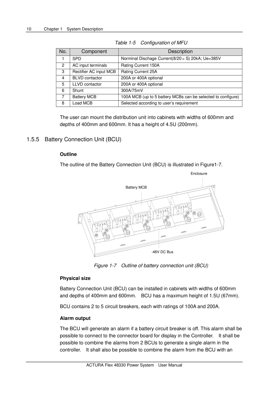
The outline of the Battery Connection Unit (BCU) is illustrated in
Enclosure
Battery MCB
Figure 1-7 Outline of battery connection unit (BCU)
Physical size
Battery Connection Unit (BCU) can be installed in cabinets with widths of 600mm and depths of 400mm and 600mm. BCU has a maximum height of 1.5U (67mm).
BCU contains 2 to 5 circuit breakers, each with ratings of 100A and 200A.
Alarm output
The BCU will generate an alarm if a battery circuit breaker is off. This alarm shall be possible to connect to the connector board for display in the Controller. It shall be possible to combine the alarms from 2 BCUs to generate a single alarm in the controller. It shall also be possible to combine the alarm from the BCU with an
ACTURA Flex 48330 Power System User Manual