20 | Chapter 2 Installation |
2.3.2Connection Of Load Cables
Loads are connected to the MCB with suitable capacity to avoid their failure to function in the case of overload. The capacity of the MCBs is recommended to be about 1.5 times of the peak value of the load capacity. The load circuit breakers are shown in Figure
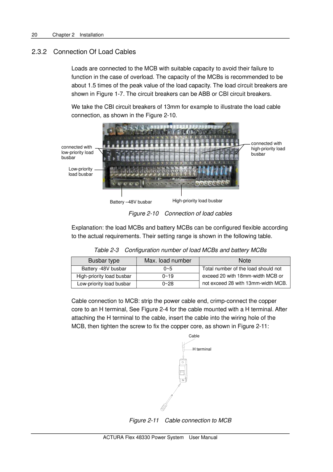
We take the CBI circuit breakers of 13mm for example to illustrate the load cable connection, as shown in the Figure
connected with |
|
| connected with |
|
| ||
|
| ||
|
| ||
|
| busbar | |
busbar |
|
| |
|
|
| |
|
|
| |
load busbar |
|
|
|
Battery | |||
Figure 2-10 Connection of load cables
Explanation: the load MCBs and battery MCBs can be configured flexible according to the actual requirements. Their setting range is shown in the following table.
Table 2-3 Configuration number of load MCBs and battery MCBs
Busbar type | Max. load number |
| Note |
|
Battery | 0~5 |
| Total number of the load should not |
|
|
|
| exceed 20 with |
|
0~19 |
|
| ||
|
|
| not exceed 28 with |
|
0~28 |
|
| ||
|
|
|
|
|
Cable connection to MCB: strip the power cable end,
Ca![]()
![]() bl
bl![]() e
e![]()
![]()
![]()
![]()
![]() H
H![]()
![]()
![]() te
te![]()
![]()
![]() rminal
rminal
Figure 2-11 Cable connection to MCB
ACTURA Flex 48330 Power System User Manual