48 | Chapter 5 Operating SCU |
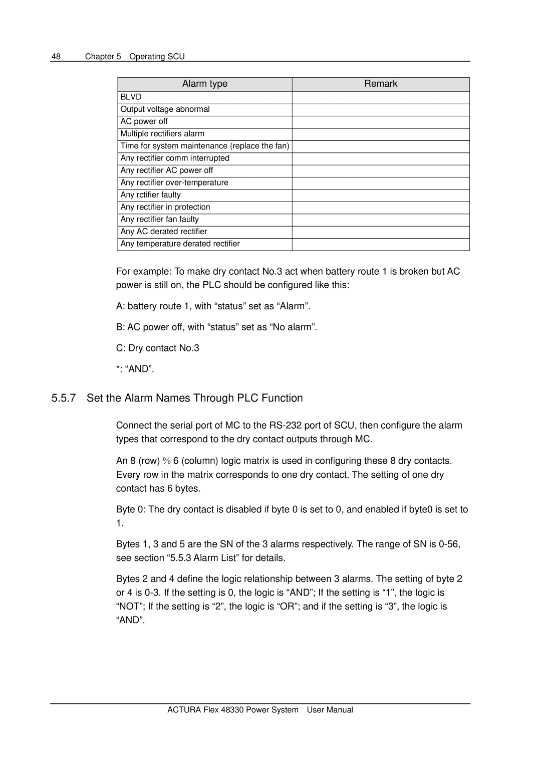
Alarm type | Remark |
BLVD |
|
Output voltage abnormal |
|
AC power off |
|
Multiple rectifiers alarm |
|
Time for system maintenance (replace the fan) |
|
Any rectifier comm interrupted |
|
Any rectifier AC power off |
|
Any rectifier |
|
Any rctifier faulty |
|
|
|
Any rectifier in protection |
|
|
|
Any rectifier fan faulty |
|
|
|
Any AC derated rectifier |
|
|
|
Any temperature derated rectifier |
|
For example: To make dry contact No.3 act when battery route 1 is broken but AC power is still on, the PLC should be configured like this:
A:battery route 1, with “status” set as “Alarm”.
B:AC power off, with “status” set as “No alarm”.
C:Dry contact No.3
*: “AND”.
5.5.7Set the Alarm Names Through PLC Function
Connect the serial port of MC to the
An 8 (row) % 6 (column) logic matrix is used in configuring these 8 dry contacts. Every row in the matrix corresponds to one dry contact. The setting of one dry contact has 6 bytes.
Byte 0: The dry contact is disabled if byte 0 is set to 0, and enabled if byte0 is set to 1.
Bytes 1, 3 and 5 are the SN of the 3 alarms respectively. The range of SN is
Bytes 2 and 4 define the logic relationship between 3 alarms. The setting of byte 2 or 4 is
ACTURA Flex 48330 Power System User Manual