Chapter 5 Operating SCU | 61 |
2. The value description of the parameters is listed below:
Table 5-13 Value description of the battery test parameters
Parameter | Range | Default | Value description | |
Battery test | 43.1V ~ | 45.2V | The monitoring module can do battery test, and record 10 sets of | |
voltage | 57.9V | test data (accessible only through the host). The battery test has to | ||
| ||||
|
|
| be started manually, then monitoring module will control the rectifier | |
Battery test time | 5 ~ 1440min | 300min | ||
|
|
| output voltage, make it lower than the battery voltage, and the | |
|
|
| ||
|
|
| battery discharge will begin. Monitoring module will stop the test if | |
|
|
| the battery voltage reaches the “Battery test voltage”, or the | |
|
|
| discharge time reaches “Battery test time”, or the battery capacity | |
|
|
| reaches “Test End Cap”. Afterwards, it will restore the rectifier | |
Test End Cap | 0.01C10 ~ | 0.7C10 | output voltage to the normal FC voltage, begin the battery charge | |
(capacity) | 0.95C10 | and switch the system to battery | ||
| ||||
|
|
| test start time/voltage and end time/voltage and battery remaining | |
|
|
| capacity will be recorded. The records can be queried through the | |
|
|
| host. | |
|
|
| During the battery test, if abnormalities occur, the monitoring | |
|
|
| module will stop the battery test automatically. | |
|
|
|
| |
Scheduled Test | Y, N | Y |
| |
Planned Test 1 |
| 00:00, Jan. 1st | When the parameter “Scheduled Test” is set to “Y”, the monitoring | |
| Month,day, |
| module will test the battery according to the 4 sets of test time. You | |
Planned Test 2 | 00:00, April 1st | |||
| hour |
| can set at most 12 sets of test time through the host. | |
Planned Test 3 | 00:00, July 1st | |||
Planned Test 4 |
| 00:00, Oct. 1st |
| |
Alarm Current | 1A ~ 100A | 10A | If the battery have not discharged within the “ShortTest Cycle”, the | |
|
|
| monitoring module will start a short test, whose operation time is | |
ShortTest Cycle | 24h ~ 8,760h | 720h | ||
|
|
| set by the parameter “ShortTest Duration”. By the end of the test, if | |
|
|
| ||
ShortTest |
|
| the difference in the discharge currents of batteries is bigger than | |
1 ~ 60min | 5min | the “Alarm Current”, the battery discharge imbalance alarm will be | ||
Duration | ||||
|
| raised. This alarm will automatically end after 5min of delay. Also | ||
|
|
| ||
|
|
| you can end it by confirming it. | |
|
|
|
| |
StableTest | Y, N |
| The stable test is conducted with constant battery current, whose | |
Enable |
| value is set through the parameter “StableTest Current”. If the | ||
|
| |||
|
|
| parameter “StableTest Enable” is set to “Y”, and the test will be | |
StableTest | 0 ~ 9999A | 9999A | ||
Current | started once the battery satisfies the test condition | |||
|
| |||
|
|
|
|
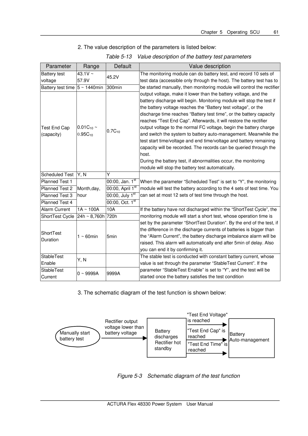
3. The schematic diagram of the test function is shown below:
|
|
| "Test End Voltage" |
|
| Rectifier output |
| is reached |
|
| voltage lower than | Battery | "Test End Cap" is |
|
Manually start | battery voltage | Battery | ||
battery test |
| discharges | reached |
|
| Rectifier hot | "Test End Time" is | ||
|
| |||
|
| standby | reached |
|
Figure 5-3 Schematic diagram of the test function
ACTURA Flex 48330 Power System User Manual
