Chapter 5 Operating SCU | 69 |
Parameter | Range | Default |
| Value description | |
|
|
|
|
|
|
Operator |
| 24V/75A/500/NONE |
|
|
|
level or |
| 24V/75A/500/MAN |
|
|
|
above |
| 24V/75A/500/AUTO |
|
|
|
|
| 24V/50A/500/NONE |
|
|
|
|
| 24V/50A/500/MAN |
|
|
|
|
| 24V/50A/500/AUTO |
|
|
|
|
| 48V/50A/500/NONE |
|
|
|
|
| 48V/50A/500/MAN |
|
|
|
|
| 48V/50A/500/AUTO | This parameter has been set according to the actual situation | ||
|
| 48V/50A/300/NONE | |||
|
| upon delivery and needs not to be changed. However, when a | |||
|
| 48V/50A/300/MAN | |||
|
| new monitoring module is used, its “System Type” should be | |||
|
| 48V/50A/300/AUTO | |||
|
| set according to the actual situation. | |||
| System | 48V/30A/300/NONE | |||
| After this parameter is changed, the monitoring module will | ||||
| Type | 48V/30A/300/MAN | |||
| restart automatically, and other parameters of the monitoring | ||||
|
| 48V/30A/300/AUTO | |||
|
| module will be changed to the defaults of the corresponding | |||
|
| 48V/30A/100/NONE | |||
|
| system type. You should change some parameters according | |||
|
| 48V/30A/100/MAN | |||
|
| to the actual situation. | |||
|
| 48V/30A/100/AUTO | |||
|
|
|
|
| |
|
| 48V/15A/100/NONE |
|
|
|
|
| 48V/15A/100/MAN |
|
|
|
|
| 48V/15A/100/AUTO |
|
|
|
|
| 48V/100A/SET/NON |
|
|
|
|
| 48V/100A/SET/MAN |
|
|
|
|
| 48V/100A/SET/AUT |
|
|
|
|
| 48V/50A/SET/NONE |
|
|
|
|
| 48V/30A/SET/NONE |
|
|
|
|
|
|
|
| |
| Change | User, Operator, Admin | The password can be 6 digits long at most. If it is shorte than 6 | ||
| Password | digits, end it with a “#” | |||
|
|
|
|
|
|
| Con Alarm | 3min, 10min, 1h, 4h, | Contstant |
| The period that an alarm sound will last |
| Voice | constant |
| ||
|
|
|
| ||
|
|
|
|
| |
Administrator | Serial | The production serial No. of the monitoring module. This parameter cannot be changed | |||
| SW Ver | The software version No. of the monitoring module. This parameter cannot be changed | |||
|
|
| |||
|
| Reflecting the jumper status of a hardware switch within the monitoring module. If this | |||
| Set Enable | parameter is set to ”N”, you are not allowed to use the jumper, nor change any | |||
|
| parameter except the battery management mode. The maintenance over the monitoring | |||
|
| module will not be affected |
|
| |
|
|
|
|
|
|
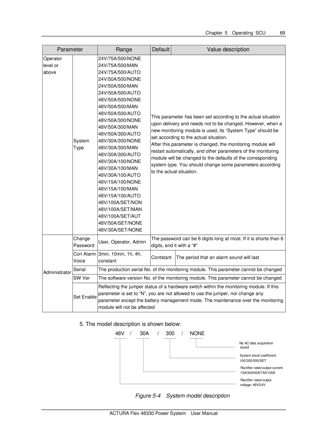
5. The model description is shown below:
48V / 30A / 300 / NONE
No AC data acquisition board
System shunt coefficient: 100/300/500/SET
Rectifier rated output current: 15A/30A/50A/75A/100A
Rectifier rated output voltage: 48V/24V
Figure 5-4 System model description
ACTURA Flex 48330 Power System User Manual