62 | Chapter 5 Operating SCU |
5.7.6Temperature Compensation Coefficient Parameters
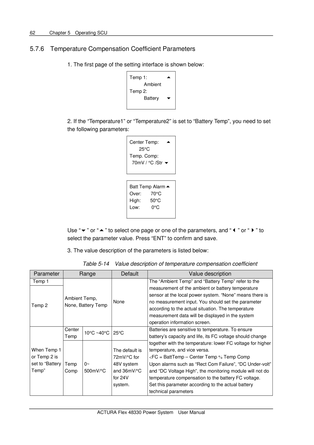
1.The first page of the setting interface is shown below:
Temp 1:
Ambient
Temp 2:
Battery
2.If the “Temperature1” or “Temperature2” is set to “Battery Temp”, you need to set the following parameters:
Center Temp:
25°C
Temp. Comp:
70mV / °C /Str
Batt Temp Alarm
Over: 70°C
High: 50°C
Low: 0°C
Use “ ” or “ ” to select one page or one of the parameters, and “ ” or “ ” to select the parameter value. Press “ENT” to confirm and save.
3. The value description of the parameters is listed below:
Table
Parameter |
| Range | Default | Value description | ||
Temp 1 |
|
|
|
| The “Ambient Temp” and “Battery Temp” refer to the | |
|
|
|
|
| measurement of the ambient or battery temperature | |
| Ambient Temp, |
| sensor at the local power system. “None” means there is | |||
| None | no measurement input. You should set the parameter | ||||
Temp 2 | None, Battery Temp | |||||
| according to the actual situation. The temperature | |||||
|
|
|
|
| ||
|
|
|
|
| measurement data will be displayed in the system | |
|
|
|
|
| operation information screen. | |
|
|
|
|
|
| |
| Center |
| 10°C ~40°C | 25°C | Batteries are sensitive to temperature. To ensure | |
| Temp |
| battery’s capacity and life, its FC voltage should change | |||
|
|
|
| |||
|
|
|
|
| together with the temperature: lower FC voltage for higher | |
|
|
|
|
| ||
When Temp 1 |
|
|
| The default is | temperature, and vice versa. | |
or Temp 2 is |
|
|
| 72mV/°C for | <FC = BattTemp – Center Temp % Temp Comp | |
set to “Battery | Temp |
| 0~ | 48V system | Upon alarms such as “Rect Com Failure”, “DC | |
Temp” | Comp |
| 500mV/°C | and 36mV/°C | and “DC Voltage High”, the monitoring module will not do | |
|
|
|
| for 24V | temperature compensation to the battery FC voltage. | |
|
|
|
| system. | Set this parameter according to the actual battery | |
|
|
|
|
| technical parameters | |
|
|
|
|
|
| |
ACTURA Flex 48330 Power System User Manual