24 | Chapter 2 Installation |
| Connector | Pin |
| Signal name |
|
| 1 |
| RS485 communication+ |
| J14 | 2 |
| RS485 communication- |
|
| 3 |
| Protection ground |
| J19 | 1 |
| 48V+ |
| 2 |
| 48V- | |
|
|
|
Mark number
E485+
E485-
PGNG
POWER+
POWER-
Logic relation
2.3.6Connection Of Temperature Sensor Cables
There are two
The user can connect the temperature sensor cables to J11 and J10.
2.3.7Connection With MODEM
Take
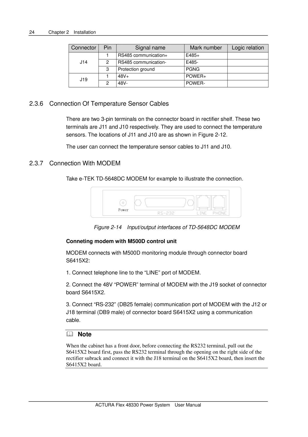
Power
Figure 2-14 Input/output interfaces of TD-5648DC MODEM
Conneting modem with M500D control unit
MODEM connects with M500D monitoring module through connector board S6415X2:
1.Connect telephone line to the “LINE” port of MODEM.
2.Connect the 48V “POWER” terminal of MODEM with the J19 socket of connector board S6415X2.
3.Connect
Note
When the cabinet has a front door, before connecting the RS232 terminal, pull out the S6415X2 board first, pass the RS232 terminal through the opening on the right side of the rectifier subrack and connect it with the J18 terminal on the S6415X2 board, then insert the S6415X2 board.
ACTURA Flex 48330 Power System User Manual