Chapter 1 System Description | 7 |
Table 1-3 Function of indicators
| LED |
| Normal |
| Abnormal |
| Cause of abnormality |
| Power indicator (green) |
| ON |
| OFF | No AC Mains Supply | |
|
|
| Blinking |
| Rectifier is under control by SCU | ||
|
|
|
|
|
| ||
|
|
|
|
|
|
|
|
| Protection indicator |
|
|
| ON |
| AC input over/under voltage, PFC |
|
| OFF |
|
| over/under voltage and over temperature | ||
| (yellow) |
|
|
|
| ||
|
|
|
|
|
|
| |
|
|
|
| Blinking |
| Communication of rectifier with SCU failure | |
|
|
|
|
|
| ||
| Alarm indicator (red) |
| OFF |
| ON |
| Output |
|
|
|
|
|
| ||
|
|
| Blinking | Fan Failure | |||
|
|
|
|
| |||
1.5.3SCU
Outline
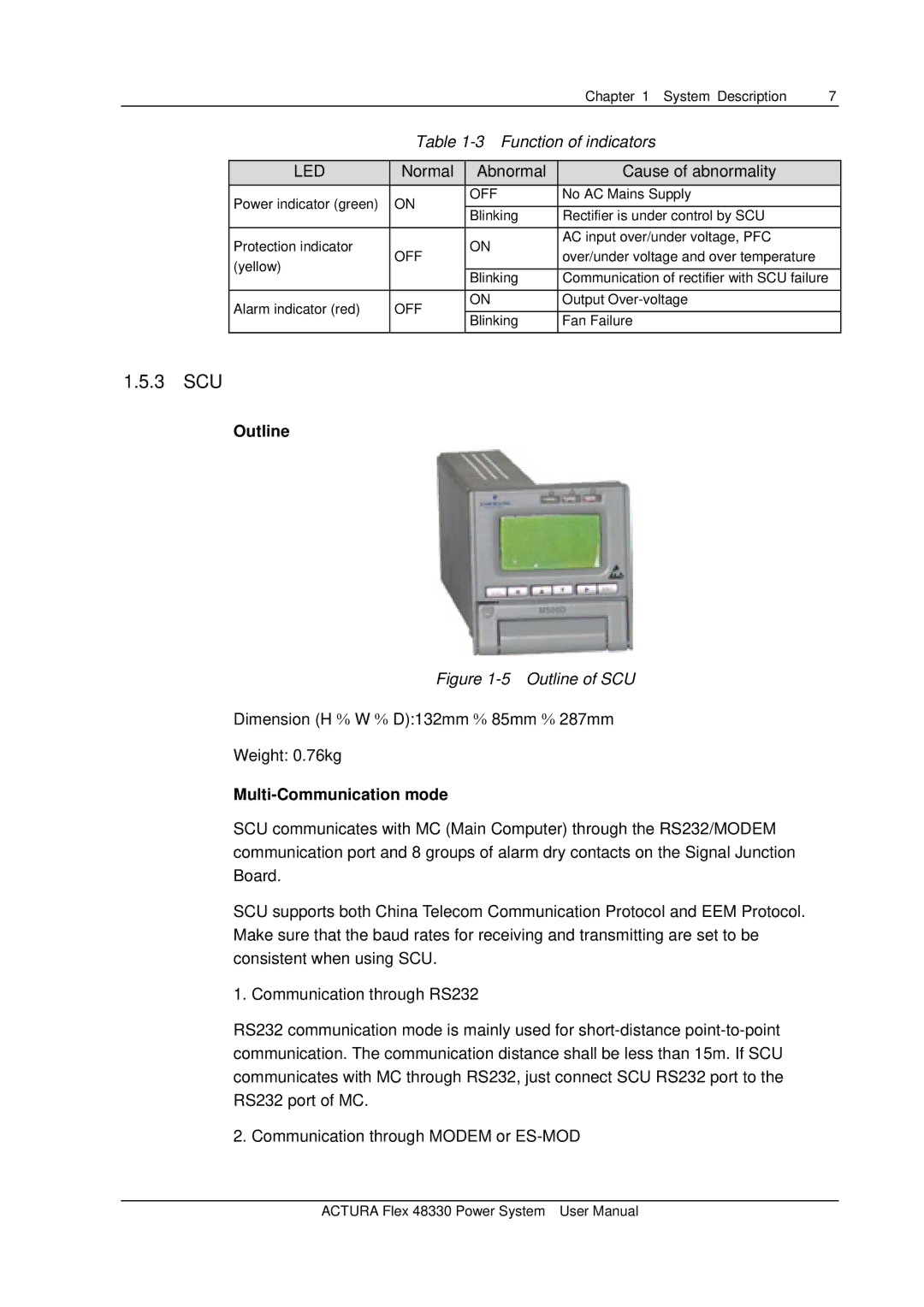
Figure 1-5 Outline of SCU
Dimension (H % W % D):132mm % 85mm % 287mm
Weight: 0.76kg
Multi-Communication mode
SCU communicates with MC (Main Computer) through the RS232/MODEM communication port and 8 groups of alarm dry contacts on the Signal Junction Board.
SCU supports both China Telecom Communication Protocol and EEM Protocol. Make sure that the baud rates for receiving and transmitting are set to be consistent when using SCU.
1. Communication through RS232
RS232 communication mode is mainly used for
2. Communication through MODEM or
ACTURA Flex 48330 Power System User Manual
