Chapter 2 Installation | 17 |
2.3 External Electrical Connection Interface
2.3.1Connection Of Input Cables
The AC input terminals, SPD, rectifier AC input switch, PE bus and PE terminals are illustrated in Figure
Connection requirements
The AC mains is connected to the AC input terminals directly. There are 6 AC input modes as shown in Table
Table 2-2 AC input modes
Item | Function unit | Amount |
| 3P+N/380V AC input |
|
|
|
|
| 1P+N /220V AC input |
|
|
|
|
AC distribution | L1+L2/220V AC input |
|
|
| |
3P/220V AC input |
| |
|
| |
|
|
|
| Terminals only - for individual rectifier AC feeds |
|
|
|
|
| 2P MCB only - for individual rectifier AC feeds |
|
|
|
|
Connection method
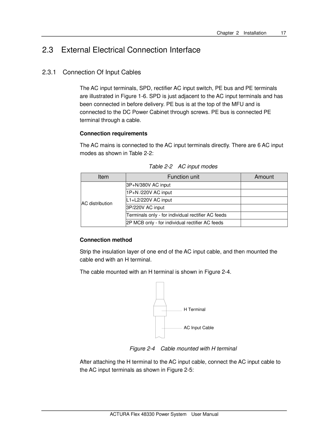
Strip the insulation layer of one end of the AC input cable, and then mounted the cable end with an H terminal.
The cable mounted with an H terminal is shown in Figure
H Terminal
AC Input Cable
Figure 2-4 Cable mounted with H terminal
After attaching the H terminal to the AC input cable, connect the AC input cable to the AC input terminals as shown in Figure
ACTURA Flex 48330 Power System User Manual