Chapter 2 – Installing and Cabling the MultiVOIP
Connecting MultiVOIP to LAN and Telephone Equipment (MVP410/810)
To connect the MultiVOIP to your LAN and telephone equipment.:
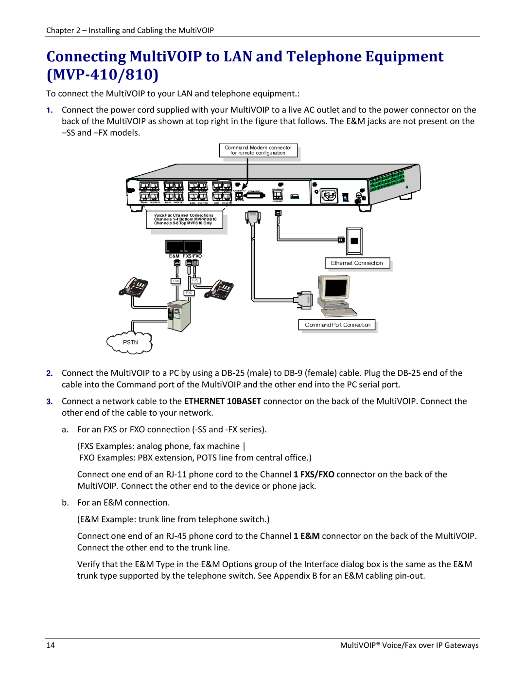
1.Connect the power cord supplied with your MultiVOIP to a live AC outlet and to the power connector on the back of the MultiVOIP as shown at top right in the figure that follows. The E&M jacks are not present on the
Command Modem connector
for remote configuration
E&M | FXS/FXO | E&M | FXS/FXO | E&M | FXS/FXO | E&M | FXS/FXO COMMAND | ETHERNET |
COMMAND | ||||||||
E&M | FXS/FXO | E&M | FXS/FXO | E&M | FXS/FXO | E&M | MODEM | 10 BASET |
FXS/FXO |
|
Voice/Fax Channel Connections
Channels
Channels
E&M FXS/FXO |
E&M | FXS |
FXO |
Ethernet Connection
Command Port Connection
PSTN
2.Connect the MultiVOIP to a PC by using a DB‐25 (male) to DB‐9 (female) cable. Plug the DB‐25 end of the cable into the Command port of the MultiVOIP and the other end into the PC serial port.
3.Connect a network cable to the ETHERNET 10BASET connector on the back of the MultiVOIP. Connect the other end of the cable to your network.
a.For an FXS or FXO connection (‐SS and ‐FX series).
(FXS Examples: analog phone, fax machine
FXO Examples: PBX extension, POTS line from central office.)
Connect one end of an RJ‐11 phone cord to the Channel 1 FXS/FXO connector on the back of the MultiVOIP. Connect the other end to the device or phone jack.
b.For an E&M connection.
(E&M Example: trunk line from telephone switch.)
Connect one end of an RJ‐45 phone cord to the Channel 1 E&M connector on the back of the MultiVOIP. Connect the other end to the trunk line.
Verify that the E&M Type in the E&M Options group of the Interface dialog box is the same as the E&M trunk type supported by the telephone switch. See Appendix B for an E&M cabling pin‐out.
14 | MultiVOIP® Voice/Fax over IP Gateways |