Chapter 2 – Installing and Cabling the MultiVOIP
c.For a DID connection.
(DID Examples: DID fax system or DID voice phone lines.)
Connect one end of an RJ‐11 phone cord to the Channel 1 FXS/FXO connector on the back of the MultiVOIP. Connect the other end to the DID jack.
Note: DID lines are polarity sensitive. If, during testing, the DID line rings busy consistently, you need to reverse the polarity of one end of the connector (swap the connections of the wires to the two middle pins of one RJ‐11 connector).
4.Repeat step 3 to connect the remaining telephone equipment to each channel on your MultiVOIP. Although
aMultiVOIP’s channels are often all configured identically, each channel is individually configurable. So, for example, some channels of a MultiVOIP might use the FXO interface and others the FXS; some might use the DID interface and others E&M, and so on
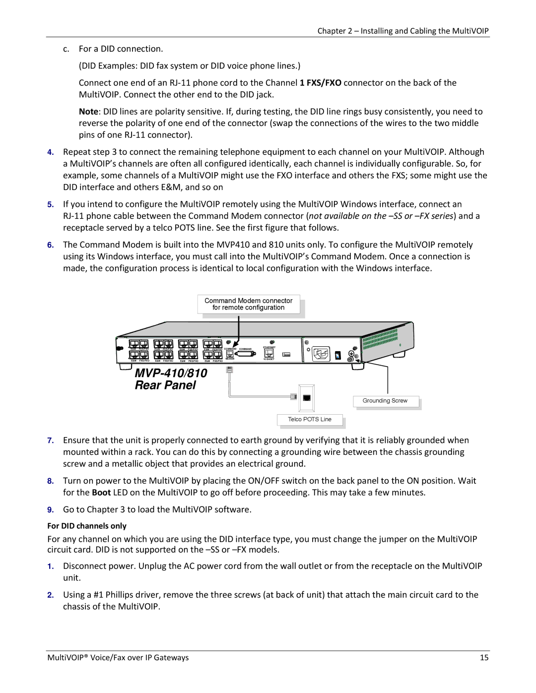
5.If you intend to configure the MultiVOIP remotely using the MultiVOIP Windows interface, connect an
RJ‐11 phone cable between the Command Modem connector (not available on the
6.The Command Modem is built into the MVP410 and 810 units only. To configure the MultiVOIP remotely using its Windows interface, you must call into the MultiVOIP’s Command Modem. Once a connection is made, the configuration process is identical to local configuration with the Windows interface.
Command Modem connector
for remote configuration
E&M | FXS/FXO | E&M | FXS/FXO | E&M | FXS/FXO | E&M | FXS/FXO | COMMAND | COMMAND | ETHERNET |
|
E&M | FXS/FXO | E&M | FXS/FXO | E&M | FXS/FXO | E&M | MODEM | 10 BASET |
FXS/FXO |
|


MVP-410/810
Rear Panel
Grounding Screw
Telco POTS Line
7.Ensure that the unit is properly connected to earth ground by verifying that it is reliably grounded when mounted within a rack. You can do this by connecting a grounding wire between the chassis grounding screw and a metallic object that provides an electrical ground.
8.Turn on power to the MultiVOIP by placing the ON/OFF switch on the back panel to the ON position. Wait for the Boot LED on the MultiVOIP to go off before proceeding. This may take a few minutes.
9.Go to Chapter 3 to load the MultiVOIP software.
For DID channels only
For any channel on which you are using the DID interface type, you must change the jumper on the MultiVOIP circuit card. DID is not supported on the
1.Disconnect power. Unplug the AC power cord from the wall outlet or from the receptacle on the MultiVOIP unit.
2.Using a #1 Phillips driver, remove the three screws (at back of unit) that attach the main circuit card to the chassis of the MultiVOIP.
MultiVOIP® Voice/Fax over IP Gateways | 15 |