1-18 Chapter 1: Product Overview
MSR
The MSR interface supports a maximum of 3 tracks of magnetic stripe information for support of ISO or JIS format cards. Activate the MSR interface by enabling it in BIOS Setup under IO Configuration. The MSR interface controller is a memory-mapped device, which can reside at system memory addresses CA000, CC000, or D0000. If MSR capability is not desired, it may be disabled through BIOS Setup.
Board BIOS
The Processor Board uses a Phoenix BIOS, which is stored in Flash ROM and easily upgraded through the network connection or serial port. The Flash EEPROM also contains the Setup utility, Power-On Self Tests (POST), and APM 1.2. The board also supports system BIOS shadowing, which enables the BIOS to execute from onboard write- protected DRAM.
The BIOS displays a sign-on message during POST identifying the type of BIOS and a five-digit revision code.
FLASH memory Implementation
The Intel E28F800B5-T70 Flash component is organized onboard as 1024 K x 8 (1 MB). While a typical PC BIOS image including video and LAN boot ROM code normally fits in 256 K on the Pentium Board and 512 K in the Pentium III/Celeron board, the boards support a 1 MB flash ROM. The current Phoenix BIOS release only requires 256 K of this 1 MB total. The Flash device contains the PC System BIOS along with the Video BIOS and LAN boot ROM which compresses the ROM images into a single binary image.
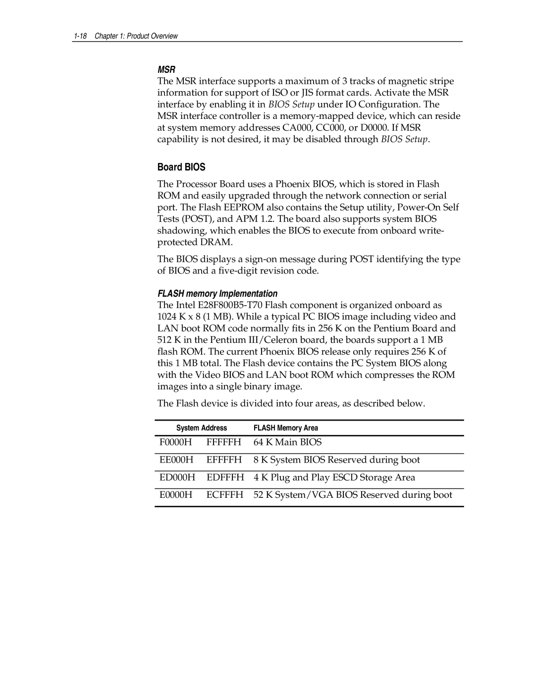
The Flash device is divided into four areas, as described below.
System Address | FLASH Memory Area |
| | |
F0000H | FFFFFH | 64 K Main BIOS |
| | |
EE000H | EFFFFH | 8 K System BIOS Reserved during boot |
| | |
ED000H | EDFFFH | 4 K Plug and Play ESCD Storage Area |
| | |
E0000H | ECFFFH | 52 K System/VGA BIOS Reserved during boot |
| | |