Chapter 1: Product Overview
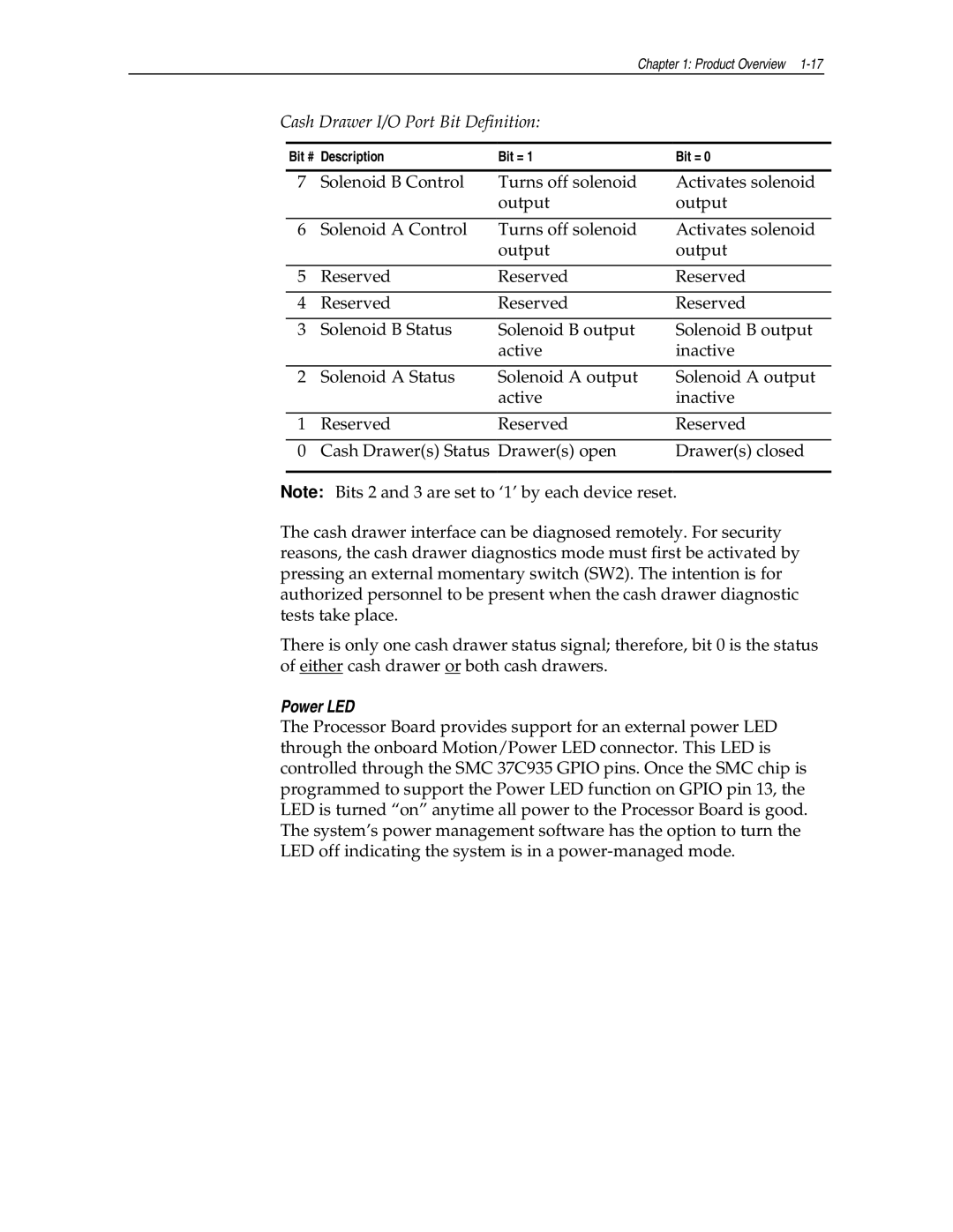
Cash Drawer I/O Port Bit Definition:
Bit # Description | Bit = 1 | Bit = 0 | |
7 | Solenoid B Control | Turns off solenoid | Activates solenoid |
|
| output | output |
|
|
|
|
6 | Solenoid A Control | Turns off solenoid | Activates solenoid |
|
| output | output |
|
|
|
|
5 | Reserved | Reserved | Reserved |
|
|
|
|
4 | Reserved | Reserved | Reserved |
|
|
|
|
3 | Solenoid B Status | Solenoid B output | Solenoid B output |
|
| active | inactive |
|
|
|
|
2 | Solenoid A Status | Solenoid A output | Solenoid A output |
|
| active | inactive |
|
|
|
|
1 | Reserved | Reserved | Reserved |
|
|
|
|
0 | Cash Drawer(s) Status | Drawer(s) open | Drawer(s) closed |
Note: Bits 2 and 3 are set to ‘1’ by each device reset.
The cash drawer interface can be diagnosed remotely. For security reasons, the cash drawer diagnostics mode must first be activated by pressing an external momentary switch (SW2). The intention is for authorized personnel to be present when the cash drawer diagnostic tests take place.
There is only one cash drawer status signal; therefore, bit 0 is the status of either cash drawer or both cash drawers.
Power LED
The Processor Board provides support for an external power LED through the onboard Motion/Power LED connector. This LED is controlled through the SMC 37C935 GPIO pins. Once the SMC chip is programmed to support the Power LED function on GPIO pin 13, the LED is turned “on” anytime all power to the Processor Board is good. The system’s power management software has the option to turn the LED off indicating the system is in a