Chapter 2: Hardware Installation |
Identifying the Cable Connectors
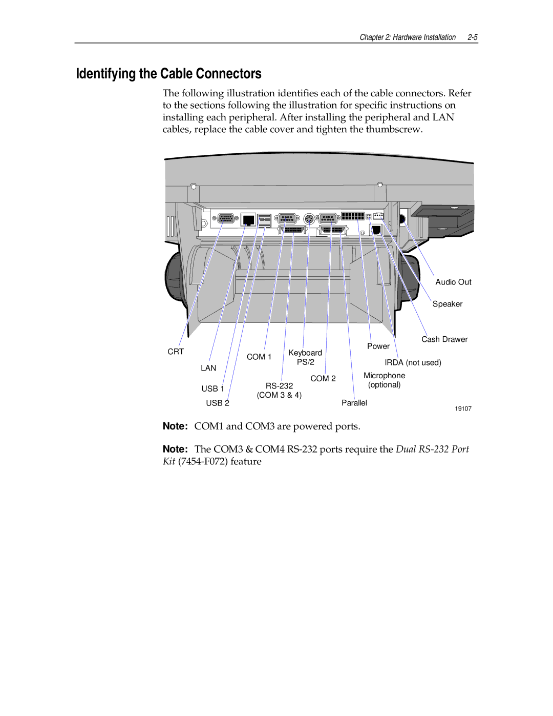
The following illustration identifies each of the cable connectors. Refer to the sections following the illustration for specific instructions on installing each peripheral. After installing the peripheral and LAN cables, replace the cable cover and tighten the thumbscrew.
|
|
|
| Audio Out |
|
|
|
| Speaker |
|
|
|
| Cash Drawer |
CRT |
|
| Keyboard | Power |
| COM 1 |
| ||
|
| PS/2 | IRDA (not used) | |
| LAN |
| ||
|
|
| Microphone | |
|
|
| COM 2 | |
|
|
| (optional) | |
| USB 1 | |||
| (COM 3 & 4) |
| ||
| USB 2 | Parallel | ||
|
|
| ||
19107
Note: COM1 and COM3 are powered ports.
Note: The COM3 & COM4
