|
|
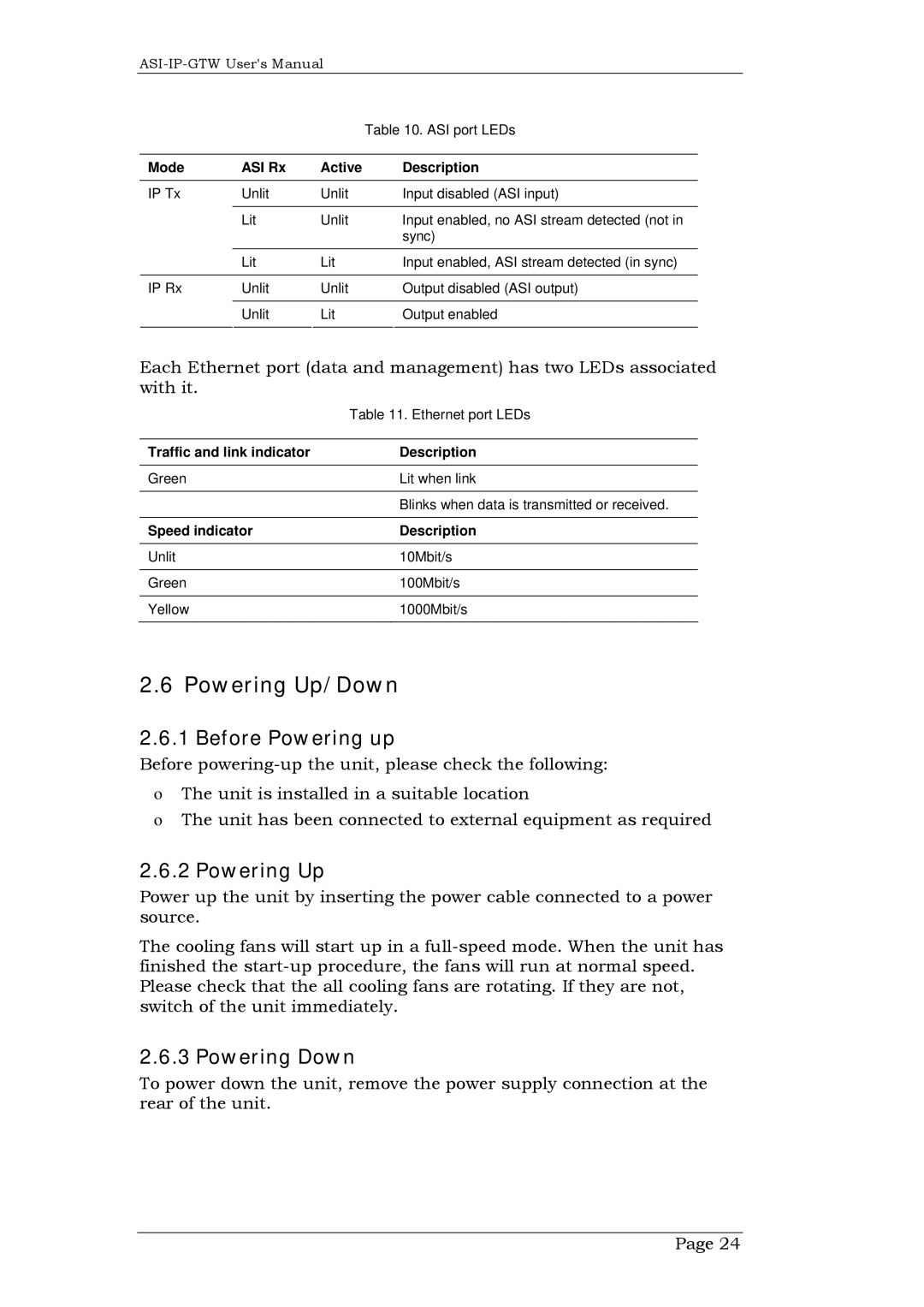
| Table 10. ASI port LEDs | |
|
|
|
|
|
Mode | ASI Rx | Active |
| Description |
|
|
|
|
|
IP Tx | Unlit | Unlit |
| Input disabled (ASI input) |
|
|
|
|
|
| Lit | Unlit |
| Input enabled, no ASI stream detected (not in |
|
|
|
| sync) |
|
|
|
|
|
| Lit | Lit |
| Input enabled, ASI stream detected (in sync) |
|
|
|
|
|
IP Rx | Unlit | Unlit |
| Output disabled (ASI output) |
|
|
|
|
|
| Unlit | Lit |
| Output enabled |
|
|
|
|
|
Each Ethernet port (data and management) has two LEDs associated with it.
| Table 11. Ethernet port LEDs |
|
|
Traffic and link indicator | Description |
|
|
Green | Lit when link |
|
|
| Blinks when data is transmitted or received. |
|
|
Speed indicator | Description |
|
|
Unlit | 10Mbit/s |
|
|
Green | 100Mbit/s |
|
|
Yellow | 1000Mbit/s |
|
|
2.6 Powering Up/Down
2.6.1 Before Powering up
Before
oThe unit is installed in a suitable location
oThe unit has been connected to external equipment as required
2.6.2 Powering Up
Power up the unit by inserting the power cable connected to a power source.
The cooling fans will start up in a
2.6.3 Powering Down
To power down the unit, remove the power supply connection at the rear of the unit.
Page 24
