o1PPS. 50 ohm TTL input for a 1
4.1.3 Operating the 1PPS/10MHz interface module
A new
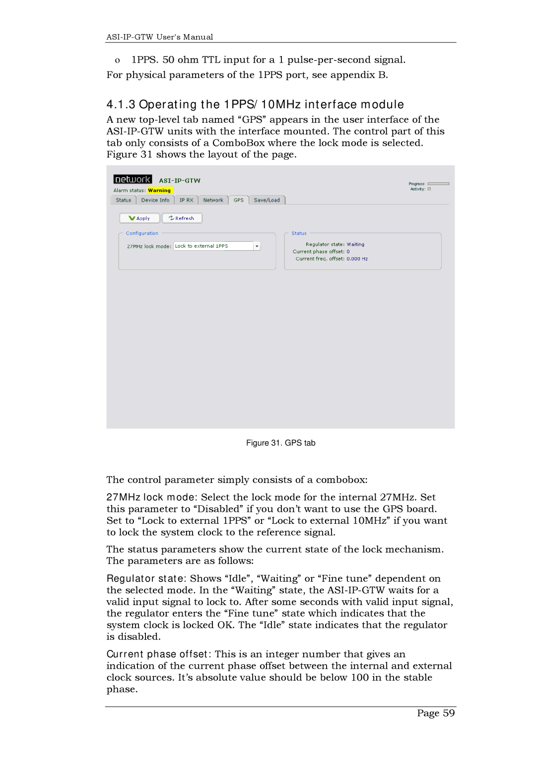
Figure 31 shows the layout of the page.
Figure 31. GPS tab
The control parameter simply consists of a combobox:
27MHz lock mode: Select the lock mode for the internal 27MHz. Set this parameter to “Disabled” if you don’t want to use the GPS board. Set to “Lock to external 1PPS” or “Lock to external 10MHz” if you want to lock the system clock to the reference signal.
The status parameters show the current state of the lock mechanism. The parameters are as follows:
Regulator state: Shows “Idle”, “Waiting” or “Fine tune” dependent on the selected mode. In the “Waiting” state, the
Current phase offset: This is an integer number that gives an indication of the current phase offset between the internal and external clock sources. It’s absolute value should be below 100 in the stable phase.
Page 59