1.5 Guided Tour
1.5.1 The User Interface
All connectors are provided at the rear panel. Configuration and monitoring of the unit is performed via a
1.5.2 Front Panel Description
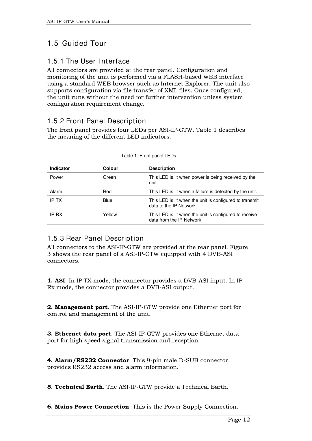
The front panel provides four LEDs per
|
| Table 1. Front panel LEDs |
|
|
|
Indicator | Colour | Description |
|
|
|
Power | Green | This LED is lit when power is being received by the |
|
| unit. |
|
|
|
Alarm | Red | This LED is lit when a failure is detected by the unit. |
|
|
|
IP TX | Blue | This LED is lit when the unit is configured to transmit |
|
| data to the IP Network. |
|
|
|
IP RX | Yellow | This LED is lit when the unit is configured to receive |
|
| data from the IP Network |
|
|
|
1.5.3 Rear Panel Description
All connectors to the
3shows the rear panel of a
1.ASI. In IP TX mode, the connector provides a
2.Management port. The
3.Ethernet data port. The
4.Alarm/RS232 Connector. This
5.Technical Earth. The
6.Mains Power Connection. This is the Power Supply Connection. Page 12
