3.5.5 Ping
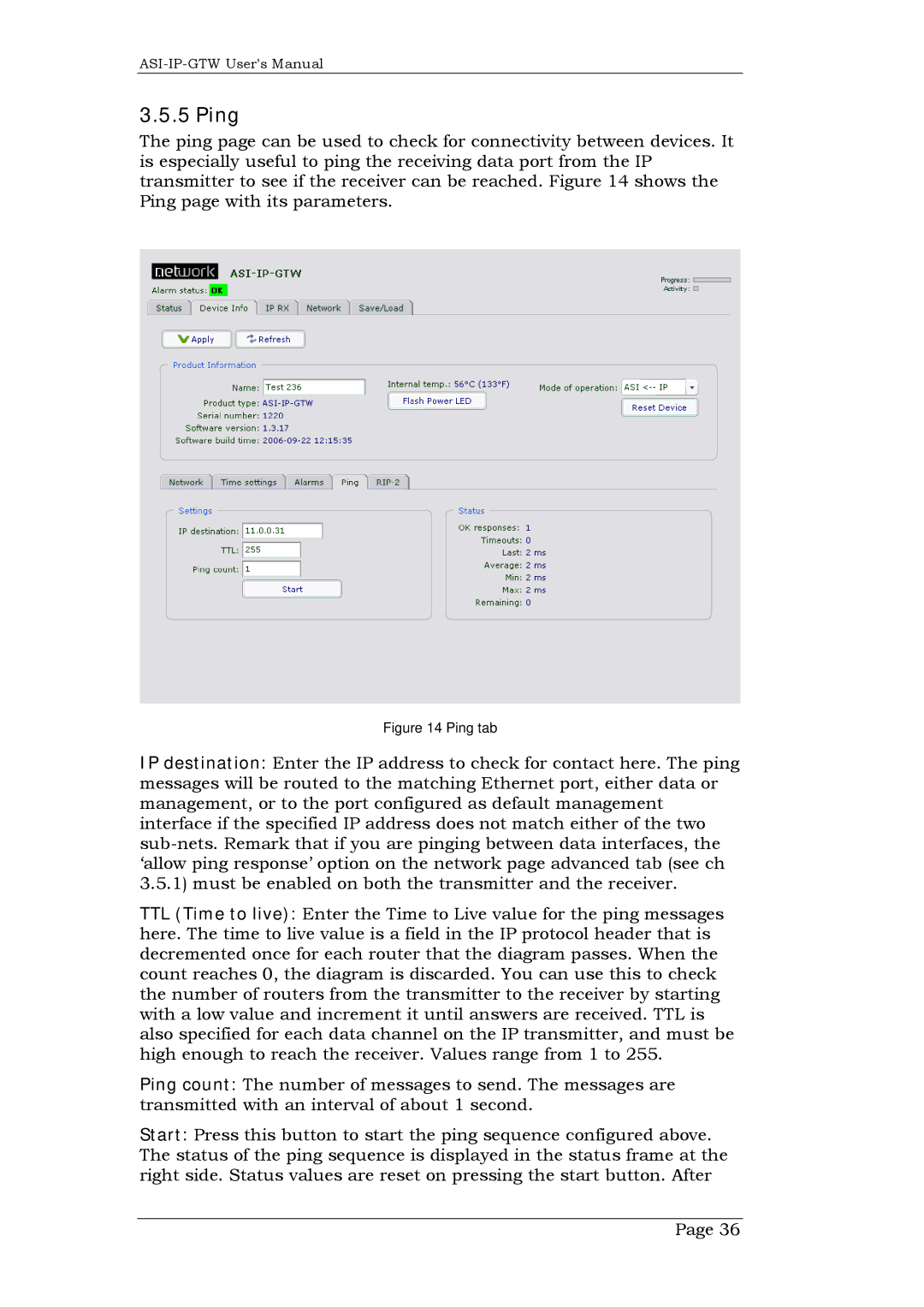
The ping page can be used to check for connectivity between devices. It is especially useful to ping the receiving data port from the IP transmitter to see if the receiver can be reached. Figure 14 shows the Ping page with its parameters.
Figure 14 Ping tab
IP destination: Enter the IP address to check for contact here. The ping messages will be routed to the matching Ethernet port, either data or management, or to the port configured as default management interface if the specified IP address does not match either of the two
TTL (Time to live): Enter the Time to Live value for the ping messages here. The time to live value is a field in the IP protocol header that is decremented once for each router that the diagram passes. When the count reaches 0, the diagram is discarded. You can use this to check the number of routers from the transmitter to the receiver by starting with a low value and increment it until answers are received. TTL is also specified for each data channel on the IP transmitter, and must be high enough to reach the receiver. Values range from 1 to 255.
Ping count: The number of messages to send. The messages are transmitted with an interval of about 1 second.
Start: Press this button to start the ping sequence configured above. The status of the ping sequence is displayed in the status frame at the right side. Status values are reset on pressing the start button. After
Page 36
