iR1200 Modem
COMPUTER
120VAC
POWER SUPPLY
GPS ANTENNA | MODEM |
(OPTIONAL) | ANTENNA |
IGNITION![]()
BYPASS
PLUG
POWER iR1200
IGNITION
GPS DATA
MODEM DATA
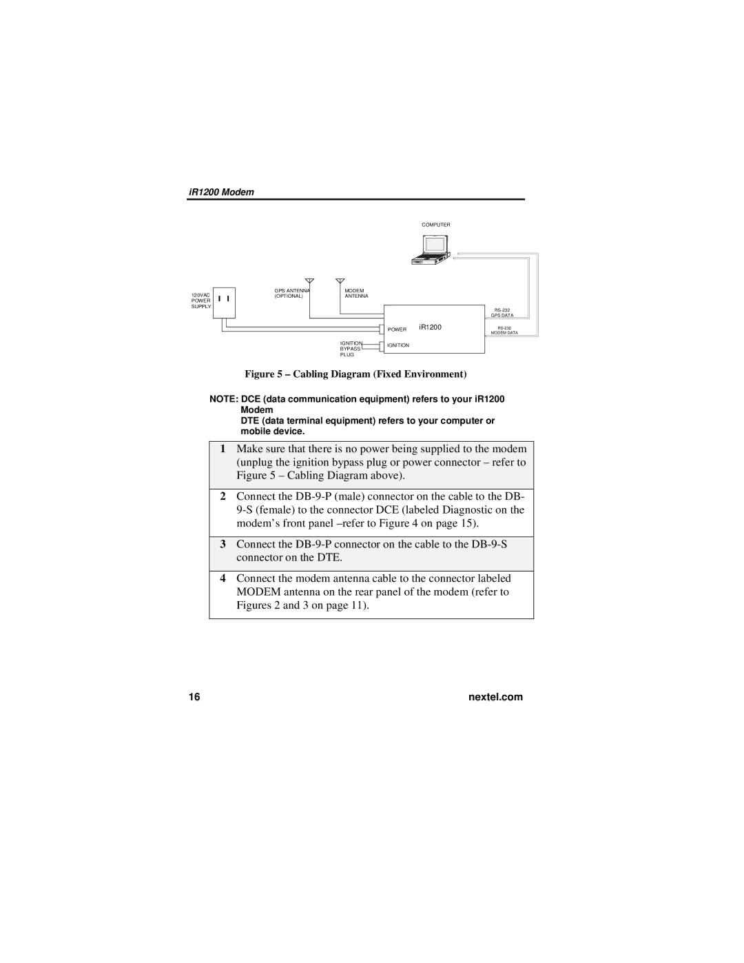
Figure 5 – Cabling Diagram (Fixed Environment)
NOTE: DCE (data communication equipment) refers to your iR1200 Modem
DTE (data terminal equipment) refers to your computer or mobile device.
1Make sure that there is no power being supplied to the modem (unplug the ignition bypass plug or power connector – refer to Figure 5 – Cabling Diagram above).
2Connect the
3Connect the
4Connect the modem antenna cable to the connector labeled MODEM antenna on the rear panel of the modem (refer to Figures 2 and 3 on page 11).
16 | nextel.com |
